FAQs
Document Actions
General
 What do I do if I run out of colors?
Q5. I've run out of colors. What to do?
A message like
  ** XAllocColorCells fails for 75 colors
  ** try the -ncolor option to reduce # of colors
when you try to start AFNI means that the program can't allocate enough color cells from the 8 bit PseudoColor colormap. Reasons this might occur are:
- You are running some other big color hog, such as Netscape or other imaging program.
- You are using a window manager (such as CDE) that uses a lot of colors for fancy decorations.
- Kill the color hog(s) so you can run AFNI first; and/or
- Setup the window manager to use less colors; and/or
- Run AFNI with the "-install" command line option; and/or
- Switch your X11 setup to be 24 bit TrueColor or 12 bit
PseudoColor.
The latter option is only possible on SGI systems, as far as I know. On our IRIX 6.2 systems, the file /var/X11/xdm/Xservers is the place where you can set the SGI X11 server to start up in 12 bit mode, if that is supported on your machine (I don't think it is supported on the Indy). I have set this file to be:0 secure /usr/bin/X11/X -bs -nobitscale -c -pseudomap 4sight \ -solidroot sgilightblue -cursorFG red -cursorBG white -depth 12This is all one line. I have just added the option "-depth 12" to the default setup shipped by SGI. If you try this, be sure to save a copy of the original file, in case it doesn't work. After you change /var/X11/xdm/Xservers, you will have to reboot the system (or otherwise force the X11 server to restart).If you want to change the SGI X11 server to start in 24 bit TrueColor mode, instead of adding "-depth 12" to the command line above, add "-class TrueColor -depth 24".
- If you are using Linux, need to reconfigure your X11 server and are using XFree86, this can be done with the program xf86config, or with some programs that come with various Linux distributions (e.g., Xconfigurator from RedHat).
How can I see the numerical value stored in a voxel?
Q11. How can I see the numerical value stored in a voxel?
A label showing the values of the current Anatomy, Function, and Threshold dataset bricks at the crosshair point is at the bottom of the rightmost column in the "Define Function" control panel. This label is only active when all three viewing windows are open at once. (This is due to the way that AFNI accesses data bricks.) If you want to see the voxel values, but don't want to see all the image windows, open all the image windows anyway and just iconify (minimize) the ones you don't care about.
I want to input some 8 bit images. How?
Q15. I want to input some 8 bit images. How?
to3d will recognize 8 bit grayscale images stored in the raw PGM format, and assemble them into a byte-value AFNI dataset, or convert them into a short-valued dataset (using the -datum command line option). You can use the netpbm utilities (available at the AFNI distribution sites), or the program xv (available here) to convert images of many different types (e.g., TIFF) to the PGM format. This makes it possible to assemble 3D (or 3D+time) grayscale datasets from modalities other than MRI (e.g., digitized photographs).
The AFNI program mritopgm will read a single 2D image in one of the formats described above and convert it to to the raw PGM format. This can be useful for incorporating 16 bit MR images into other documents that require 8 bit files; for example
mritopgm im.1.08 | pnmtotiff > im.tifwill produce a TIFF image from a 2D MRI slice.
There is no provision at present for colored 3D datasets in the AFNI package.
What functions are used in program waver?
Q17. What functions are used in program waver?
There is no documentation or publication describing the "Cox" (or -WAV default) waveform generated by program waver. The formula for the impulse response function is as follows:
for t in (-infinity .. delaytime)
  waver = 0

for t in (delaytime .. delaytime+risetime)
  waver = peak * z( (t-delaytime)/risetime )

for t in (delaytime+risetime .. delaytime+risetime+falltime)
  waver = (1+undershoot) * peak * z( (delaytime+risetime+falltime-t) / falltime ) - undershoot

for t in (delaytime+risetime+falltime .. delaytime+risetime+falltime+restoretime)
  waver = -undershoot * peak * z( (delaytime+risetime+falltime+restoretime-t) / restoretime )


for t in (delaytime+risetime+falltime+restoretime .. infinity)
  waver = 0
This is pretty straightforward, allowing the user to control the time breakpoints of the function: delay part, rise part, fall part (including a post-undershoot), and a restoration part (from the undershoot).
The function z(x) above is a function that rises smoothly from z=0 for x<0 to z=1 for x>1. In waver.c, this function is programmed as
for x in (-infinity .. 0 )
  z = 0

for x in ( 0 .. 1 )
  z = 0.50212657 * ( tanh(tan(0.5*PI * (1.6*x-0.8))) + 0.99576486 )

for x in ( 1 .. infinity )
  z = 1
The peculiar looking formula for the meaty part of z(x) was chosen partly by trial and error graphing, and partly because I think that the combination tanh(tan()) is a cool function. It looks OK, and there really isn't enough data to distinguish between different types of curves that make this 0->1 transition used to model the rise and fall of the BOLD response. The graph below shows z(x) for x between -0.5 and 1.5.
![[Graph]](/images/waver_ztone.gif)
The -GAM gamma variate waveform option is derived from Mark Cohen's work (NeuroImage 6:93-103, 1997). Here is a comparison plot:
![[Graph]](/images/waver_both.gif)
The -WAV and -GAM data for this graph were produced with the commands
  waver -dt 0.25 -xyout -inline 1 20@0 -undershoot 0 -delay 1 -rise 4 -fall 5
  waver -dt 0.25 -xyout -inline 1 20@0 -GAM
The actual graph was produced with program xmgr, available here.
If you use the gamma variate waveform t**b * exp(-t/c), note that the time-to-peak is b*c and the FWHM of the peak is approximately 2.4 * sqrt(b) * c (the approximation is valid for b > 1). Mark Cohen's values are b = 8.6 and c = 0.547, giving time-to-peak = 4.7 s and FWHM = 3.8 s.
Are there any man pages for AFNI programs?
Q19. Are there any man pages for AFNI programs?
No. The closest thing is that most programs take the command line switch "-help", which will print out some information on the usage. We try to keep this information up-to-date (unlike the manuals, which are updated on a time-available basis, which means hardly ever).
For larger scale issues that aren't covered in the manuals, there are also the myriad README.* files, and, of course, this FAQ list.
Show me the Anterior and Posterior commissures!
The grayscale image display of my dataset doesn't seem right.
Q21. The grayscale image display of my dataset doesn't seem right.
The default mapping from image voxel values to grayscale values is to compute the histogram of the displayed slice, then map the 2% point on the cumulative distribution to the lowest grayscale and the 98% point to the highest grayscale. Intermediate voxel values are mapped linearly to the intermediate grayscale levels in the colormap. This technique of clipping off the smallest and largest values works well for MRI data, which are often plagued by a few bright spots caused by arterial inflow artifacts.
You can switch to map the smallest slice value to the lowest grayscale and the largest slice value to the highest grayscale using the "Disp" control panel in the image window: just select the "Min-to-Max" switch. This is probably a good idea when you are viewing a mask image or other artificially generated data.
When you are making a montage, whichever mode you use is applied to each slice separately and the final montage is pasted together from the results. If you want to control the scaling from voxel values to grayscales so that all slices are treated equally, see the answer to Q8.
How do I control the overlay colors?
Q22. How do I control the overlay colors?
Overlay colors are determined by the "Function" dataset. The threshold slider on the "Define Function" control panel interacts with the threshold data brick from that dataset to determine which voxels will be cut off and not be overlaid in color. You can use the "**" control below the threshold slider to control its range, in powers of 10. If the threshold data brick has statistical parameters attached to it (in the .HEAD file), then the nominal p-value is shown below the threshold slider.
For the fim (etc.) dataset types, the threshold brick is fixed. For the fbuc ("bucket") dataset type, any brick within the dataset can be used as the threshold. If the current "Function" dataset is the bucket type, then a pair of choosers labeled "Func" and "Thr" are activated. The latter lets you pick the threshold brick; the former lets you choose the functional brick.
The colors are computed from the functional brick. The colors of the data that pass the threshold are determined by the color slider to the right of the threshold slider, and by the "range" controls to the far right/bottom. By default, "autoRange" is on, which means that the maximum value in the functional dataset brick is mapped to the top value on the color slider (1.0). By clicking "autoRange" off, you can enter a value in the data field below, and that will be the value mapped to 1.0. For example, if you want to have values of 5.0 mapped to 1.0, you can type "5.0" in that field. Functional values over 5.0 are treated as equivalent to 5.0 in this mapping. If you want to turn those off entirely, you can do so by setting the top color of the color slider to "none" (click in a color panel to change its color value). Then choose the mapping range appropriately to get the colors you want with the remaining part of the color slider.
The number of color steps is chosen by the menu labeled "#" just below the color slider. The toggle switch labeled "Pos?" allows you to change the color slider data range from the default [-1..1] to be [0..1]. This is appropriate if your functional data is always non-negative (or if you just don't want to see the negative functional values). There is no way to display only negative function (unless you just set all the positive colors to "none").
It is also possible to change the upper range of the color slider away from the default value of 1.0. This is done using the Button-3 popup menu attached to the "Inten" label at the top of the slider. This feature, and other facets of the color slider, are more fully described in the file README.setup.
N.B.: It is important to realize that a functional value of zero will never cause a color overlay, even if it is in the range of one of the color slider panes.
[Answer edited 04 Mar 2000]
How do I get a list of Talairach coordinates?
Q23. How do I get a list of Talairach coordinates?
If you want a list of the coordinates of the centers of mass of clusters of voxels in a dataset, the command line program 3dclust will do this for you. You can apply a threshold to the dataset to clip off the undesired voxels, and then set geometric criteria for the clustering operation.
If you want a list of the coordinates of all the voxels above some threshold, there really isn't a way to do that. It could be grafted into program 3dmaskave without much trouble, but so far there has been no such demand.
So how do the clustering paramerters "rmm" and "vmul" work?
Q24. So how do the clustering parameters "rmm" and "vmul" work?
The clustering options (to programs 3dclust and 3dmerge, among others), put together voxels that are nonzero and spatially contiguous. The first step is usually to threshold the dataset in some way (this can be done on the command line of 3dclust, or can be done ahead of time with 3dmerge, 3dcalc, etc.).
The geometrical criterion for spatial contiguity is defined by the parameter "rmm". A nonzero voxel is defined as being in the same cluster as another nonzero voxel if their centers are within a distance of rmm millimeters. In a 3D lattice of cubical voxels with edges of length L, the range of common values of rmm are:
- L < rmm < 1.4142 L
This will directly connect voxels that share a common face (nearest neighbors), but no others. - 1.4142 L < rmm < 1.732 L
This will also connect voxels that share an edge (2nd nearest neighbors), but have no nonzero voxel in common in the corner between them. - 1.732 L < rmm < 2 L
This will also connect voxels that share a corner (3rd nearest neighbors), but have no nonzero voxel in common in the corners between them.
The parameter "vmul" is used to delete (set to zero) voxels in clusters whose volume is less than vmul microliters (a microliter is a cubic millimeter). This is particularly useful when datasets have been resampled to a fine grid in Talairach coordinates. There may be small patches of above-threshold voxels that are smaller than one of the original data voxels. Thus, vmul should be at least as large as the volume of an original voxel, and you may want it to be 2 or 3 times larger than that.
Cluster Erosion and Dilation
The -1erode and -1dilate options to
3dmerge can be used to further massage the shapes of
clusters. The basic idea is to try to cut off small "necks" (or
peninsulas) that might connect larger regions, as in this
picture:
   xxxxxxx         yyyyyyy
   xxxxxxx         yyyyyyy
   xxxxxxxaaaaaaaaayyyyyyy
   xxxxxxx         yyyyyyy
   xxxxxxx         yyyyyyy
This is easy to see in 2D, but hard to see when it is all twisted through 3D space--what looks like 2 separate clusters of activation may actually be detected by 3dclust (or 3dmerge) as 1, because of a small neck (like the a voxels) connecting the two larger regions.
By eroding the outer edges, the a voxels would be removed, along with the outer edges of the the x and y regions. Dilation from the surviving x and y regions will restore the x and y regions back to about what they were before, but the a neck will not come back (much).
For a single voxel neck, as illustrated above, setting the erode pv parameter to 50 should delete the a voxels, since you are requiring that 50% of the neighbors be in the cluster for non-erosion. Since there are 6 neighbors (in 3D, and assuming you have set rmm to cluster only nearest neigbors), and the a's only have 2 cluster neighbors each, they will be gone. So will the corner x and y voxels. Dilation will restore the corners, and also the first a voxels that stick out of the big regions, but the rest of the neck will be history.
Other Editing Options
The program 3dmerge has a number of other "editing options"
that can be used to manipulate the data prior to clustering. Most
useful among these, perhaps, is the -1thresh option, which
will threshold the data before clustering. When using the newer
bucket type of datasets (e.g., as generated by FIM+), you
might need to select the correct sub-bricks for the data to be
clustered and the thresholding. In 3dmerge, this is done
with options -1dindex and -1tindex, respectively.
These two options were just added to program 3dclust as well
[16 Sep 1999]. If you are using an earlier version of the
AFNI package, the only way to use a bucket dataset with
3dclust is to first use 3dmerge with the appropriate
-1dindex and -1tindex options (and maybe
-1thresh) to create a temporary dataset with the desired
properties. (Or you could upgrade to the current AFNI.)
[Answer last changed 23 Sep 1999]
I wrote a plugin that worked, so why does it fail when I download a new version of AFNI?
Q25. I wrote a plugin that worked, so why does it fail when I download a new version of AFNI?
The internal data structures that define a dataset may be altered when a new version of AFNI is released. If your plugin is not recompiled using the new header files, then it will be accessing the wrong locations in the C structs and it is unlikely that good things will results. If you download a new copy of the AFNI package, you should recompile all your own (private) plugins to be safe, after you recompile all the AFNI libraries. ("Private" means a plugin that isn't distributed with AFNI from MCW.)
At startup, AFNI now checks the compilation date of plugins and prints out a warning message if a plugin was compiled before the AFNI main program. This is intended to remind you of such potential conflicts. If you are only using plugins from MCW, this message should not occur, since the normal Makefile order builds the main program first and the plugins last.
How do I make a GIF animation?
Q26. How do I make a GIF animation?
The program whirlgif can create an animated GIF (for inclusion on a Web page, like this one) from a sequence of single frame GIFs. These can be created from pnm images saved out of AFNI using the program ppmtogif (part of netpbm). Whirlgif is included in the AFNI source code package, but must be compiled manually with "make whirlgif". See the output of "whirgif -help" for what documentation there is. (Whirlgif was written by Kevin Kadow; all I did was add the "-help" option.) The csh script gmovie that is included in afni_src.tgz can be used to convert a buch of PNM format images to a single animated GIF. You may need to tweak its operation for your particular needs, though.
Another program that does something similar is gifsicle. You can search for this (and many other things) at Google.
[29 Jun 2001] Now that AFNI can write GIF images directly from an image viewer (if you have netpbm installed -- AFNI just pipes the .ppm format through program ppmtogif), this makes it pretty easy to make animated GIFs. After saving the requisite .gif files, then issue one of the following commands
  whirlgif -loop -time 20 fred*.gif > anim.gif  # if you have whirlgif compiled
  gifsicle -d 20 -l -O fred*.gif > anim.gif     # if you have gifsicle compiled
[05 Aug 2001] AFNI now has the capability to run gifsicle (preferred) or whirlgif directly to produce Animated GIFs. AFNI can also use the program mpeg_encode to write a sequence of images into an MPEG-1 animation. These programs are supplied with the AFNI source code, but are not compiled by default. You can make them by issuing the command
make gifsicle mpeg_encodeThis will leave the program files gifsicle and mpeg_encode in the AFNI source code directory. You then must move these files to be in your path (perhaps in the same place you keep the rest of the AFNI executable files).
If these programs are installed, the image-viewer Disp control panel will have two new items: "Save Anim GIF" and "Save Anim MPG". Choosing one of these means that the next image sequence you write out using the image-viewer Save button will be written to a single animation file, rather than a set of single-image files. Note that if Save One is also selected, the choice of an animation format will override that selection, and the animation will be written. (Recall that Save One is the only way to write out a montage image layout.)
Can I resample to a non-cubical grid using AFNI?
Q28. Can I resample to a non-cubical grid using AFNI?
No. I understand that the AIR program from Roger Woods (at UCLA) can do this. Check out http://bishopw.loni.ucla.edu/AIR3/index.html.
If your goal is to resample your functional data in Talairach space back to a grid that is similar to the original data grid, this may not be such a good idea. In the transformation to Talairach coordinates, the original data grid is rotated and rescaled (and rescaled differently in different parts of the brain, for that matter). The original slices are not likely to be parallel to the new coordinate system, or have the same thickness. Resampling to a coarse non-cubical grid can make these changes very visible, and produce funny looking artifacts.
How would you configure a Linux system for AFNI?
Q29. How would you configure a Linux system for AFNI?
A good Intel/Linux system (but not really cheap) would be
- 800 MHz+ MHz Pentium III/IV or Athlon (but not Xeon - doesn't provide much speedup).
- As much RAM as you can cram in (256-1024 MB).
- Dual 18 GB SCSI disk drives (or dual 36 gigs, or more!).
- Some data backup system: DDS-3 tape, CD recorder, ....
- 20-21'' monitor, configured to run at 1600x1200 (or an LCD
panel!).
- Even better are dual display systems, which I'm using and really enjoying.
If you are not comfortable installing Linux yourself, there is a large number of vendors who will build a computer for you, install Linux (and Windows), and ship you the system. A list of companies that sell computers with Linux pre-installed can be found here -- one vendors I have used successfully in the past is ASL Workstations [this is not an endorsement, just a statement of fact].
AFNI itself is developed to be compatible with all the Unix systems to which I have regular access. This means (in order of importance) Intel-x86/Linux, SGI-MIPS/IRIX, Sun/Solaris, Mac OS X, and HP-PA/HP-UX. Compatibility with other systems is by luck, mostly. I have heard of people using AFNI on IBM/AIX, DEC, and OpenBSD. Not having one of these systems handy, I can't help if you run into trouble on one of them.
How can I do Region-of-Interest (ROI) analyses?
Q30. How can I do Region-of-Interest (ROI) analyses?
A few tools for selecting voxel subsets and extracting their data for external analysis are included with AFNI 2.20. These tools are quite new and crude, and (God willing) will be improved as time goes on. Nonetheless, it is possible to do some useful work with them now.
The ROI stuff is mostly implemented as a set of plugins. These all have extensive help, so I won't give all the details here. You may need to write some C programs to calculate useful results after extracting the data you want.
Selecting a ROI: plugin "Draw Dataset"
This plugin lets you draw values into a dataset brick. The idea is
to start with a dataset that is all zeros and then draw nonzero
values over the desired regions. An all zero dataset of a size
equivalent to an existing dataset can be created using the
"Dataset Copy" plugin. Another way to create a starting
point for a mask dataset would be to use the "Edit
Dataset" plugin or the 3dmerge program (e.g., to pick
out all voxels with a correlation coefficient above a
threshold).
Normally, you would create the mask dataset as type "fim". This would allow it to be displayed as a functional overlay on the anatomical background.
Mask datasets tend to be mostly zeros. You can use the ability of AFNI to read/write compressed datasets to save disk space. See the file README.compression and the plugin "BRIK compressor" for details.
To be useful, a mask dataset must be created at exactly the resolution of the datasets it will be used with. This means that if you create a mask at the anatomical resolution, the functional datasets to which you apply it must be at that resolution also. This isn't a problem in the +acpc or +tlrc coordinate systems, but is an annoyance in the +orig data. Sorry about that. (But see the program 3dfractionize, described below.)
The drawing plugin is rather tedious to use. An adaptation of it, written by Rick Reynolds (formerly of MCW), is also now distributed with AFNI. This appears as Gyrus Finder on the Plugins menu. It allows you to set some bounding planes, and then select voxels inside these planes based on the gray level of the anatomical dataset. You can then clean up the results using drawing tools. The only documentation for this plugin is in its online help.
Averaging Data Defined by a ROI Mask: program
3dmaskave
This program lets you compute the average over a ROI of all voxel
values from an input dataset. (It is also possible to extract all
the voxel values and save them for other analysis.) The ROI is
defined by a mask dataset. The average value is computed for each
sub-brick in the input, so you can use this to create an average
time series. The output is written to stdout - it can be redirected
(using '>') into a file. For more information, try
"3dmaskave -help". An alternative to this command-line
program is the similar plugin "ROI Average", which you can
use interactively from within AFNI.
Averaging Several Distinct ROIs at Once: program
3dROIstats
This program, by Tom Ross of MCW, can do something similar to
3dmaskave, but does a separate average for each separate
value found in the mask file. In this way, you can have multiple
masks defined in one mask file, the first defined by putting 1 into
some voxels, the second by putting 2 into some voxels, etc.
(3dmerge can do this using the -1clust_order
option, for example. Or you could use the Draw Dataset
plugin to draw multiple anatomical ROIs using distinct voxel
values.) Then 3dROIstats can extract the average over each
ROI for you, all in one operation (vs. running 3dmaskave
many times).
Extracting Data from ROIs into an ASCII File: program
3dmaskdump
This program will write one line for each voxel that meets the mask
criteria. Multiple values (from multiple sub-bricks of multiple
datasets) can be written to each line. This format is suitable for
import into a spreadsheet program (say) for further analysis and
graphing.
[03 Oct 2000] The new program 3dUndump can be used as an inverse to 3dmaskdump, in that it will let you create a dataset from a list of voxel coordinates and values.
Resampling a ROI Mask to a Lower Resolution: program
3dfractionize
This new program (07 Feb 1999) lets you take a mask dataset
produced at higher resolution (e.g., by drawing over an anatomical
dataset) and resample it down to a lower resolution (e.g., a
typical EPI dataset). The new mask can then be used in the normal
ways described above. Fractionize refers to the fact that
the program computes the fraction of each output voxel that is
occupied by nonzero input voxels, handling the cases of possible
overlap correctly (we hope). Normally, you would clip off voxels
that had too small a fraction touched by the input mask. This
clipping can be done with 3dfractionize itself, or later
using one of 3dmerge, 3dcalc, or 3dmaskave. At
present, the only documentation for 3dfractionize is the
output of the command 3dfractionize -help.
The following documentation is by Michael S. Beauchamp of the
NIMH:
One of the most useful ways to visualize FMRI data is an average MR
time series from a group of voxels. AFNI makes this easy,
with the "ROI Average" plug-in or the "maskave" stand-alone
program. The user inputs a mask BRIK specifying which voxels to
average, and a 3D+time BRIK containing the time series data.
AFNI then outputs a text file with the average value at each
time point (and standard deviation, if desired) which can be
graphed in Excel or any other plotting program.
Some difficulties arise when the mask BRIK and the 3D+time BRIK have different coordinate spaces or voxel dimensions. In these cases, 3dfractionize may be used to translate between the different datasets.
Also see this useful page from Brown University.
[Answer last changed 26 May 2000]
What are the angles reported from 3dvolreg?
Q31. What are the angles reported from 3dvolreg?
The names are chosen from the angles used in describing the motions of aircraft or ships. (Imagine lying down with your arms out, pretending that you are an airplane. It is not necessary to make zooming noises during this mental exercise.)
- Roll is the angle about the Inferior-to-Superior (I-S) axis. It corresponds to the motion one makes when shaking the head "NO".
- Pitch is the angle about the Right-to-Left (R-L) axis.
It corresponds to the motion one makes when nodding the head
"YES".
(This is the motion my Chairman is supposed to make when I ask for a large raise.) - Yaw is the angle about the Anterior-to-Posterior (A-P) axis. It involves rocking the ear towards the shoulder.
The new [12 Feb 1999] program 1dplot makes it possible to graph the "-dfile" output from 3dvolreg to the display, and thence to a PostScript file. It can also be used to graph arbitrary *.1D format files, but for better control over such graphs, you should use program xmgr, available here, or use some other dedicated graphing program.
By the way, the displacement estimates output by 3dvolreg are in millimeters, and the angles are in degrees. This fact is mentioned in the output of 3dvolreg -help, but some people seem not to notice. One reason for these choices is that the typical FMRI experiment (at least with experienced normal volunteers) results in motions of about 1 mm and/or 1 degree, in my experience.
If you would like short description of how 3dvolreg works, see the end of file README.registration. For a longer description, you can download a PostScript preprint of a paper recently published in Magnetic Resonance in Medicine [Dec 1999].
[Answer last changed 10 Dec 1999]
What are "Arg list too long" messages?
Q32. What are "Arg list too long" messages?
Errors like this occur when you create a command line that is larger than the operating system allows. This is a particular problem on SGI IRIX systems. If the problem is arising with to3d, one way around it is to use internal wildcard expansion on the input filenames - see Q12.
If the problem is that you want to input a lot of files to a statistics program, such as 3dRegAna, another approach is needed. If you make the last option on the command line be "-@", then the program will copy the contents of standard input (stdin) to the tail of the command line. (This feature is part of the AFNI package, not a part of Unix.) You can use this in one of two ways:
- 3dRegana -@ < filename
where filename contains the information to copy onto the command line. (This file may have linebreaks -- it doesn't have to be one big line. No line should have over 4000 characters, though.)
- 3dRegana -@ << ENDSTRING
options
more options
....
ENDSTRINGThis method uses a feature of the shells csh and sh, where the standard input of the program is read from the input file (rather than the user's terminal) up until a line that matches the characters just to the right of the "<<" -- in this case, I've used "ENDSTRING" as this marker. An advantage of this method is that the inputs for the program are in the same shell script that you are using to run the program, rather than being in a separate file. If you choose to use this technique, a glance at the man pages for your shell of choice would be in order.
[20 Apr 2001]: This method is now implemented into the following programs:
If there is a program missing from this list for which you need this functionality, please let me know. It only requires pasting 4 lines of C code into the program to add this capability.
3dANOVA2 3dANOVA3 3dANOVA 3dbucket 3dcalc 3dDeconvolve 3dDetrend 3dfim 3dfim+ 3dFriedman 3dKruskalWallis 3dMannWhitney 3dmaskdump 3dMean 3dmerge 3dNLfim 3dOverlap 3dpc 3drefit 3dRegAna 3dROIstats 3drotate 3dStatClust 3dTcat 3dttest 3dUndump 3dvolreg 3dWavelets 3dWilcoxon to3d
Note Well: Each group of characters read in by "-@" separated by "whitespace" (blanks, tabs, newlines) will be appended as a separate argument to the program.
- In particular, you cannot embed a blank in an argument using quotes, unlike if the argument were actually on the command line.
- The shell does not do filename expansion (globbing) on "-@" data, so you do not escape or quote wildcards such as the *?[] characters.
- If you use the "<<" input method described above, the shell does do $ variable expansion on the input lines, so any dollar signs in the input stream need to be escaped with the backslash \ character: \$ (that is, unless you want shell variables to be expanded there).
- Not all the above programs have been tested with "-@"; please let me know if there are any problems.
How can I avoid running out of memory in to3d?
Q33. How can I avoid running out of memory in to3d?
to3d assembles the new dataset into RAM before writing it to disk in the .BRIK file. As it is reading 2D slices from the input files, it will need to have in memory one input file at a time and also the entire new dataset. If the input file comprises all the new dataset, this means that twice as much RAM is needed during input as is needed to store the new dataset brick(s). (The code was written this way because our image reconstruction software gives us our images as individual slice files. In this case, the overhead is just the amount of memory needed for one slice, which is trivial.)
To avoid this problem, the "-in:1" switch was added to to3d. If you use this, then only one 2D slice will be read out of each input file at a time. When inputting a big 3D or 4D file, this results in somewhat more disk I/O, but saves a lot of memory.
On HP-UX systems, another problem is that HP seems to ship the Unix kernel configured so that each running program can only access 64 MB of RAM, no matter how much the system actually has. To fix this, the super-user (root) has to use the SAM program (part of HP-UX) to adjust the kernel parameters, and then rebuild the operating system. Ugly, but true.
How can I avoid having AFNI convert the symbolic links in my session directory names?
Q34. How can I avoid having AFNI convert the symbolic links in my session directory names?
You can do this using the AFNI_NOREALPATH environment variable. For details, see file README.environment.
What does the "Intensity" computed by FIM mean?
Q35. What does the "Intensity" computed by FIM mean?
The "FIM intensity" is defined on page 22 of the manual afni200.ps. It is the parameter alpha in the least squares fit of each voxel time series x(t) to the model
x(t) = alpha * r(t) + a + b*t + noisewhere r(t) is the reference waveform you supply. Thus, if you double r(t), alpha will be halved; alpha is the amount of r(t) present in x(t), as computed by linear regression.
The "Compute FIM+" menu item in an AFNI graph window has the ability to compute percent change in addition to the fit coefficient alpha. In this module, "percent change" is defined from the baseline in the absence of function, not from the average time series value including the function. r(t) is linearly scaled and shifted to be between 0 and 1 (no matter what the input range actually is), and then the fit above is computed. The baseline is a + b*tmid, where tmid is the middle time point, and the percent change is 100*alpha/baseline. (If other orts are present, baseline is defined as the average value of the fit of all the orts, including the implicit orts 1 and t, whose coefficients are a and b in the equation above.)
Note that this will often produce some huge percent changes of low significance outside the brain (where the baseline is small), so that the range of the "% Change" sub-brick will be large (cf. Q49). For proper color overlay display of 5% (say) signals, you will have to turn off the autoRange toggle on the "Define Function" control panel, and enter the desired range in the parameter box directly below.
Finally, note that the -percent option of 3dfim does something slightly different: it computes the absolute value of the percent change from the time series mean (which will include the mean value of the function). Why is this different from the "FIM+" module within AFNI itself? There is no good reason. (See also the answer to Q41.)
How can I count the number of voxels above threshold in a functional dataset?
Q36. How can I count the number of voxels above threshold in a functional dataset?
There are 2 slightly clumsy ways to do this counting, one from the command line and one from a plugin. They are basically the same.
From a plugin: use the ROI Average plugin. Choose the Source and Mask datasets to be the same. Choose the sub-bricks to be the same, and to be the one you want to threshold on (e.g., for fico datasets, the correlation coeffient is in sub-brick #1 -- in general, you can use the Define Datamode->Misc->Func Info item to get information about a dataset's sub-bricks). Use the Range control in the plugin to set the range of values from the sub-brick you want to include (e.g., for fico datasets, you might set the range to be 0.5 to 1.0 to include all voxels with correlation coefficient between these values). Then press Run+Keep and you'll get a popup window with the summary information you want.
The same thing can be done using the 3dmaskave command line program - which isn't surprising, since the plugin and the program are almost identical, except for their interfaces. See the output of 3dmaskave -help for the details.
What you are doing is creating a mask on-the-fly, by applying a threshold to a dataset sub-brick, rather than by drawing one manually with the Draw Dataset plugin. If the dataset were already thresholded externally (e.g., in 3dmerge), then you wouldn't have to use the Range controls, and just use the whole dataset itself as a mask for itself. Voxels that are zero in the mask sub-brick, either because they were zero ahead of time or were thresholded away using the Range controls, do not count in the calculation of the output.
A related problem is to count the number of voxels that meet two criteria; for example, the number of voxels in a FIM+ dataset with correlation coefficient greater than 0.4 and that have a Best Index value of 4. This can be done using 3dmaskave (but not the plugin) with a command like
3dmaskave -mask name+orig -mindex 3 -mrange 0.4 1.0 -dindex 1 -drange 4 4 name+origSub-brick #3 (Correlation) is thresholded, keeping only values between 0.4 and 1.0 (inclusive). Then sub-brick #1 (Best Index) voxels whose value is between 4 and 4 (inclusive) are counted up. (Program 3dinfo can be used to find out what sub-bricks are stored in a dataset.) The output of 3dmaskave will be something like
  +++ 987 voxels survive the mask
  4 [130 voxels]
The first line says that 987 voxels were above the correlation threshold of 0.4 that was set with the -m* options to 3dmaskave. The second line says says that the average value of the selected voxels was 4 (not surprising here, since only allowed values of exactly 4 were counted), and that 130 voxels went into this average.
How can I more easily control the initial colors in the functional overlays?
Q37. How can I more easily control the initial colors in the functional overlays?
There are two ways to control this, both of which involve setup files.
The first is to set some values in your .Xdefault (or .Xresources) file in your home directory, which is read by the X11 graphics server when you login. When AFNI starts, it will query the server for resource values that start with the string AFNI. The full list of values that the program looks for is given in the sample file AFNI.Xdefaults, which is distributed with the AFNI source code.
The second (and better) method is described in detail in README.setup.
How can I "upsample" an image to higher resolution?
Q38. How can I "upsample" an image to higher resolution?
Higher resolution is not achievable, but smaller pixel sizes are. (Resolution means the ability to distinguish features; merely going to a smaller pixel size will not help. But it can make an image look better, especially when zoomed.)
The new [16 Apr 1999] program imupsam will take as input a 2D image (floats, shorts, PGM, or PPM) and upsample it to a finer resolution, using 7th order polynomial interpolation in each direction.
What is the format of a .BRIK file?
Q39. What is the format of a .BRIK file?
A .BRIK file contains nothing but voxel values. If a dataset has 1 sub-brick, which is 100x100x100 voxels, and the values stored are shorts (2 bytes each), then the .BRIK file will have exactly 2,000,000 bytes. All the formatting information is stored in the .HEAD file. For example, this .BRIK file would also be compatible with a 1000x100x10 array. The dimensions are stored in the .HEAD file, along with the voxel sizes, location in the magnet, and other such auxiliary information.
What is the format of a .HEAD file?
Q40. What is the format of a .HEAD file?
I thought you'd never ask. However, the answer may not be entirely satisfactory.
The .HEAD file for an AFNI dataset is in ASCII, so you can view it with a normal text editor (e.g., vi - the editor for real men). The data within are organized into what I call "attributes", which are named arrays of floats, integers, or characters (strings). A sample float attribute is
  type = integer-attribute
  name = DATASET_DIMENSIONS
  count = 5
  256 256 124 0 0
This particular array defines the voxel array dimensions. An example of a character array attribute is
  type = string-attribute
  name = IDCODE_DATE
  count = 25
  'Mon Apr 15 13:08:36 1996~
Note that the data for a string attribute starts with a single ' character, and that the number of bytes is given by the count parameter. The ASCII NUL character is replaced by the tilde ~ so that the .HEAD file can be edited manually, if need be. On input, tildes will be replaced with NULs.
Unfortunately, I've never documented the list of attributes that are used by AFNI. The use that AFNI makes of each attribute can be inferred (perhaps) by perusal of the code in thd_dsetdblk.c; the many macros defined in 3ddata.h will be needed to decipher this routine. The dataset reading code (see file thd_opendset.c and routines called therein) requires a minimal set of attributes to be able to decipher a dataset; for example, the DATASET_DIMENSIONS attribute above is required. There are also some attributes that are not mandatory for a dataset to be successfully constructed from a .HEAD file; for example, the IDCODE_DATE attribute above is not required. Attributes that AFNI doesn't know how to deal with are ignored. This makes it possible for a program to tuck extra information into the .HEAD file and not cause trouble.
The order in which the attributes occur is not important. AFNI reads all the attributes into memory at once, then searches for them by name as needed in the dataset construction code. On the other hand, an improperly constructed attribute (e.g., one with the count value given incorrectly) may make the .HEAD file unreadable at all. This is why manually editing a .HEAD file should be done very carefully.
[28 Mar 2001]: I've finally documented the attributes in a .HEAD file, and you can read that information here.
What are the FIM+ sub-bricks?
Q41. What are the FIM+
sub-bricks?
The Compute FIM+ menu item (on the FIM menu in a
graph window) calculates a "functional bucket" dataset that
contains up to seven sub-bricks. In each voxel, these values are
computed from the data time series x(t) as follows
(cf. Q35):
- Fit Coef
This is the least squares estimate to the fit coefficient a in the time series model
x(t) = a r(t) + b + c (t-tmid) + orts + noise ,
where r(t) is the reference (or ideal) waveform, and tmid is the time in the middle of the scan. Note that magnitude of a will depend on the magnitude of r(t), since doubling r(t) will perforce require halving a. - Best Index
When more than one time series r(t) is in the *.1D file chosen as the ideal, then this is the index of which one gave the best fit (in the least squares sense) to the time series model. The index starts at 1. If the different r(t)'s are just time shifted versions of each other, then the Best Index can be used as a crude estimator for hemodynamic delay. - % Change
If r(t) is normalized to vary between 0 and 1, then this is equal to 100 a/baseline. Since the user may input an r(t) that is not normalized to lie between 0 and 1, the program allows for this in the calculation. The baseline used is equal to a min[r]+b, plus the sum of the averages of the orts (including the constant and linear trend).Please note that the % Change computed in the interactive AFNI is not the same as that computed in the program 3dfim. This is because the two programs were written by two different people. The difference is that 3dfim uses the time series mean as the baseline, rather than the calculation described above. The difference is usually small. When will this difference be reconciled? [begin music] The answer, my friend, is blowing in the wind. [end music]
- Baseline
This is just the baseline estimate described above. It is not computed by default, but can be enabled from the Compute FIM+ menu. - Correlation
This is the correlation coefficient of x(t) with r(t), after detrending the baseline and the orts:
xd(t) = x(t) - b - c (t-tmid) - orts .
Then the correlation coefficient estimate is
rho = sum[ xd(t) r(t) ] / { sum[ xd(t)**2 ] sum[ r(t)**2 ] }**0.5 .
In terms of the Fit Coef a, this can be written as
rho = a sum[r(t)**2]**0.5 / { a**2 sum[r(t)**2] + sum[noise**2] }**0.5 .
This shows that as a gets large and positive, the correlation tends to 1.If r(t) is a square wave ("boxcar" function), then thresholding on rho is mathematically equivalent to thresholding a t-statistic between the "on" and "off" intervals. This elementary fact has appeared several times in the FMRI literature, but still does not seem to be widely known.
One disadvantage of using rho as a measure of activation magnitude is that its definition not only contains the BOLD response a r(t), but also contains the noise level. That is, two otherwise identical voxels with different amounts of noise will have the same a (and the same % Change), but will have different values of the correlation coefficient. For this reason, I usually recommend using either the Fit Coef or the % Change as a measure of the BOLD response.
- % From Ave
This is the same as % Change, but the denominator is each voxel's average rather than baseline. For positive signals, this will result in a smaller value than the % Change, since the baseline will be larger. For negative signals, the opposite will occur.
[Requested by Andrzej Jesmanowicz of MCW, 08 Sep 1999.] - Average
This is the average value of each voxel's time series, as computed by the linear regression underlying the FIM calculations. - % From Top
This is the percent signal change again, but the denominator is each voxel's peak value rather than the base or average value. - Topline
This is the estimate of each voxel's peak value, as fit by the linear regression. - Sigma Resid
This is the estimate of each voxel's residual standard deviation, after the linear regressors (ideals and orts) have been subtracted.
By default, the FIM+ computations calculate the following values:
Fit Coef Best Index % Change Correlation
You can select a different subset from the FIM+ submenu of
a graph window's FIM menu. It is also possible to set a
different default set of calculations by modifying the environment
variable AFNI_FIM_MASK. Other environment variables can
also be used to affect the FIM and FIM+
calculations - see file README.environment.
[Answer last changed 04 Jan 2000]
I duplicated a plugin and then edited it, but can't get both it and the original to work at once!
Q42. I duplicated a plugin and then edited it, but can't get both it and the original to work at once!
This problem can arise when two separate plugins have routines with the same name, which is likely to arise when you create one plugin by copying and changing another. The two ways around this problem are
- Change all the function names in the copy.
- Declare all functions (in both plugins) as static (except for PLUGIN_init).
I installed the AFNI package, but when I try to run a program, I get a 'not found' message!
Q43. I installed the AFNI package, but when I try to run a program, I get a 'not found' message!
Your problem is that the shell you are using is not finding the program you are trying to run. After you compile the AFNI binaries (or unpack them from one of the binary distributions), you need to install them in a place in the list of directories that the system searches for executable files. This list is called your "path". If you are using the shell csh or tcsh, you can add a directory to the path the system gives you with a command like
set path = ( $path /new/directory/name )If you are using the Bourne or Korn shells (sh, bash, or ksh), the equivalent action is
PATH=${PATH}:/new/directory/name ; export PATH
Normally you would put such commands in the shell startup file in
your home directory (.cshrc, .profile, or
.bashrc, depending on your shell). This file contains a
list of commands that will be executed when the shell starts. Note
that editing this startup file will not cause the
file to be re-executed, so the path will not change immediately.
For this to happen, you will have to logout and login again, or
otherwise start a new shell.
The "shell" is the program that you are typing into when you issue commands explicitly (rather than by pointing and clicking). It handles things like wildcard expansions, environment variable settings, etc. You should probably become familiar with the capabilities of your shell by reading the Unix man page for it (print it out and use it for bedtime reading).
When trying to compile AFNI, I get messages like "Xm/Xmall.h not found"!
Q44. When trying to compile AFNI, I get messages like "Xm/Xmall.h not found"!
Your problem is that the Makefile isn't finding the Motif library files on your system. One possible cause is that the compiler isn't searching for the files in the right place. The search path is controlled by the -I and -L switches to the compiler. You may need to modify these in your Makefile, assuming you can find the place where Motif is installed.
If you are using Linux, the more likely cause is that you don't have Motif installed. Motif is the software that is used to build the AFNI graphics interface (layered on top of X11 and Xt). Motif is not free software (unlike X11 and Xt), and so doesn't come automatically with Linux. You have to buy it, at about US$100-150 per machine. RedHat sells it, as do a number of other places. AFNI also works fairly well with the free LessTif libraries (but be sure to get the latest version).
[15 May 2000] Motif source and binaries are now available free from their owner, the Open Group. Go here for more information, or try here.
If i change a timeseries file, why doesn't Rescan *.1D re-read it?
Q45. If I change a timeseries file, why doesn't Rescan *.1D re-read it?
As you may have discovered, Rescan *.1D only reads new filenames, and won't re-read data from filenames that it has seen before. This is a feature, not a bug. Really.
As I recall my thinking at the time, the reason is that when you select a *.1D file to be an ideal, AFNI makes an internal copy of it (this happens at other places, too) - a copy is made because you are allowed to edit the ideal inside AFNI. So if the *.1D file were re-read after it was altered, you'd expect the internal copies (e.g., the one being plotted as the ideal) to be updated as well. But then AFNI would have to keep track of what functions have a copy of a now modified time series, and then update them. This would be too much like work.
If you are repeatedly modifying a timeseries file (e.g., using waver), Rescanning, and deciding if it is acceptable, I would recommend renaming the new file each time (e.g., to elvis_1.1D, then elvis_2.1D, etc.).
Can you supply me with the images from the Talairach-Tournoux Atlas?
Q46. Can you supply me with the images from the Talairach-Tournoux Atlas?
No! These images are copyrighted, and duplication/distribution of them would get me into big trouble with the publisher of the Atlas (Thieme). Sorry about that.
How can I use the volume renderer to deal with arbitrary datasets?
Q47. How can I use the volume renderer to deal with arbitrary datasets?
The design of the rendering plugin was motivated by several factors:
- Lack of time to deal with the complexity of non-identical grids and coordinates in the overlay and underlay bricks.
- The fact that this was the first time I ever used volume rendering.
- The belief that people were most likely to use this on Talairach datasets, which are usually identical in conformation.
It is possible to force a dataset into this mold, but it is a little clumsy. There are 3 steps:
- Use the 3ddup program to make a "warp-on-demand"
(.HEAD file only) copy of a dataset; for example:
 3ddup -prefix aaa anat+orig
 3ddup -prefix fff r1:time@1+orig
makes the datasets aaa+orig and fff+orig, which are copies of the anatomical and functional datasets. - Run AFNI, open up the Datamode control panel, and turn on "Warp Anat on Demand" and "Warp Func on Demand". Set the "Resam mode" for Anat and Func, and maybe set the Resam voxel size, too (default here is 1 mm). Then use the "Write Anat" and "Write Func" buttons to write out the aaa and fff datasets (if necessary, you'll have to use Switch so that these are the current datasets). This will give them .BRIK files. (Do NOT use "Write Many" to write them out in one operation!) Exit AFNI now.
- Unless these datasets are axial (that is, 3dinfo shows
that they are stored in "-orient RAI"), you next must create axial
slice versions of these dataset. This is done with the
3daxialize program, as in
  3daxialize -prefix aaa_ax aaa+orig
  3daxialize -prefix fff_ax fff+orig
You can now delete aaa+orig.* and fff+orig.*, since the axialized datasets contain the same data, just reordered into axial slices.
Some people want to know how to resample one dataset so that it is forced to be on the same grid and volume as another. This can be done using the Write function of AFNI, as well. The trick is to know that the output grid and volume for the Function dataset are defined by the current Anatomy dataset. For example, suppose you have an angiography dataset you want to visualize on the same 3D grid/volume as another anatomical dataset. The first step is to use 3ddup as above on the angio dataset, but to also make it be a functional type, as in the command below:
3ddup -fim -prefix angio_dup angio+origThen you can start AFNI, set the Anatomy to be the master dataset whose 3D grid/volume you want to use, and set the Function to be angio_dup; you may also want to alter the Func resample mode. Then do Write Func. Quit AFNI, and do the 3daxialize thing on angio_dup+orig, and then change the result back to be an anatomical dataset:
  3daxialize -prefix angio_ax angio_dup+orig
  3drefit -spgr angio_ax+orig
  rm -f angio_dup+orig.*       [this is optional, of course]
You will now be able to view the new dataset angio_ax as an anatomical underlay, either in the normal image viewing windows or in the rendering plugin, and it will cover the same volume as the anatomy master dataset you chose when you wrote to disk.
[Answer last changed 21 Oct 1999]
How can I turn off the "Splash" window that AFNI starts with?
Q48. How can I turn off the "Splash" window that AFNI starts with?
If you really want to do this (why? don't you like my face?), set the Unix environment variable AFNI_NOSPLASH. For more details, see file README.environment.
How can I suppress the spuriously large % Change values from FIM+?
Q49. How can I suppress the spuriously large % Change values from FIM+?
Voxels in the noise region have a very small baseline, and so can have a very large % Change value reported. This huge value can cause the true smaller % Change values to be lost in the quantization to 16 bits used in the final step of FIM+. To avoid this problem, set the Unix environment variable AFNI_FIM_PERCENT_LIMIT to something reasonable - 100, say. [08 Sep 1999: this setting also sets a limit on the value of the % From Ave sub-brick - see Q41.]
While I'm on the subject, the environment variable AFNI_FIM_BKTHR can be used to set the threshold for the suppression of the noise background in the FIM and FIM+ computations. For more details on these (and other) environment variables in AFNI, see file README.environment.
Is there a faster way to average datasets than using 3dcalc?
Q50. Is there a faster way to average datasets than using 3dcalc?
Yes; program 3dmerge with the -gmean option should execute faster and can also deal with more than 26 inputs. Also, program 3dMean does essentially the same thing, and is specialized for this purpose (so has many fewer options to wade through than 3dmerge).
3dcalc uses a general purpose expression parser that I wrote for other purposes (part of an imaging radar simulation) in Fortran, back about 1984. It isn't very efficient compared to compiled C code, but it is handy for "one off" calculations.
After 3dmerge, I don't have any threshold data?
Q51. After 3dmerge, I don't have any threshold data?
Generally, this is correct (the exceptions are when the -keepthr and the -doall options are used). You can use the program 3dbucket to assemble sub-bricks from multiple datasets into a new dataset. AFNI can then view these "functional bucket" datasets using any one sub-brick as the color-determining intensity and any one sub-brick as the threshold value. See the documentation files /pub/dist/doc/3dbucket.ps and /pub/dist/doc/buckets.ps for more details on how to create buckets.
How can I do a t-test on time series data?
Q52. How can I do a t-test on time series data?
There are two possible ways to do intra-dataset comparisons to get a t-test result. The first is to use program 3dttest. At present, this requires breaking the input dataset into pieces, 1 sub-brick per dataset, since 3dttest can only read 1 sub-brick datasets. You could do this break up with the command line program 3dbucket, used once for each sub-brick to be extracted. This would be ugly, but possible.
The second way is to use the FIM analysis with the ideal set to be equal to 1 for the "on" periods and equal to 0 for the "off" periods. A correlation with such a 0-1 valued ideal function is mathematically equivalent to a t-test between the "on" and "off" time points. The correlation coefficient that is returned can be converted to a t-statistic via the formula
  t = sqrt(n) * r/sqrt(1-r*r)
  where r = correlation coefficient
  n = number of degrees of freedom = N-2
  N = number of points in the time series used in the analysis.
There is no particular reason to do this conversion, since the results of a correlation analysis are statistically identical, and since AFNI will show the nominal p-value for either type of statistic.
[Later]: If you are doing a correlation with multiple ideals, then the program assumes you are approximately optimizing over a 1 dimensional set of functions. This changes the distribution - it is no longer equivalent to a t-test after the above transformation. Instead, if you want to convert the correlation coefficient to some more familiar statistic, you should use the equation
  Nt-Nort-Nfit     r**2
  ------------ * -------- = F(Nfit,Nt-Nort-Nfit)
  Nfit         1-r**2
  where
  Nt   = number of points in time series used in correlation
  Nfit = number of fitting dimensions (1 or 2 in FIM)
  Nort = number of "orts" (2 in the default setup)
(assuming the null hypothesis that the time series consists of Nt samples of i.i.d. N(0,1) deviates).
[Answer last changed 28 Feb 2000]
What are some known problems with the AFNI package?
Q53. What are some known problems with the AFNI package?
Alas, no nontrivial program is without bugs or other flaws. The ones that I know about are listed below.
- Plugins: The plugin startup code searches all the
directories given in the environment variable
AFNI_PLUGINPATH for plugin libraries. If this environment
variable is not set, then the PATH variable will be used
instead. The use of PATH has caused problems at 2 sites,
for reasons unknown. Therefore, it is best to set
AFNI_PLUGINPATH directly before starting the afni program.
In the C shell:
setenv AFNI_PLUGINPATH /plugin/directory
In the Bourne or Korn shellsAFNI_PLUGINPATH=/plugin/directory ; export AFNI_PLUGINPATH
Logically, these go best in your startup files (e.g., .cshrc, .profile, etc.). You can also set environment variables in your .afnirc file; for details, see README.environment.Note that the Makefiles and binary distributions install the plugins in the same directory as the other AFNI binaries. If you wish to avoid trying to load plugins altogther, the switch -noplugins can be used on the afni command line. You may also set the environment variable AFNI_NOPLUGINS; this too will prevent the plugin startup code from being executed.
Local Plugins: If you develop your own plugins (see /pub/dist/doc/afni_plugins.ps), you must be sure to compile them with the same Makefile that was used to compile the AFNI package. Otherwise they may not be loaded correctly. This problem has arisen with our SGI systems, which have several different binary execution modes (selected by compile-time options to cc), which are not compatible with each other (e.g., a -n32 module can't be mixed with a -64 module).
Plugin Date Checking: When new versions of the package are released, I don't guarantee binary compatibility with older plugins. One reason is the need to add new data structures to the AFNI internals. The result is that all plugins and command line programs need to be recompiled with each release of AFNI. To remind you of this (if you are developing your own plugins), the plugin startup code checks the plugin compilation date vs. the AFNI compilation date - if the plugin is compiled before afni itself, a warning message will be displayed.
- FIM+ and 3dfim: As mentioned in Q35 and Q41, the internal FIM+ and batch program 3dfim don't calculate exactly the same % Change. They also don't prune the low-intensity voxels from the calculation in exactly the same fashion. There are probably other differences, as well, which are ultimately due to the different histories of these two codes.
- Byte Ordering: As discussed in Q18, AFNI now keeps a flag in each dataset header file noting the byte order of the information in the bricks. However, older (pre-May 1998) files won't have this flag. When transported between computer systems, such datasets will behave peculiarly. The solution is to properly mark old datasets with their byte order. The method for doing this is described in AFNI Necronomicon (README.environment).
- Illegal Float BRIKs: It is possible to write a set of
bits to a floating point file that does not represent a legal
number (this cannot happen with an integer-valued file). Floating
point bricks are assumed to contain legal numbers, and AFNI
programs will likely fail badly (e.g., go into an infinite loop) if
this assumption is violated.
There are two ways to avoid this problem:
(1) Use program float_scan. It can read a floating point file, patch (set to zero) illegal values, and write them back to the disk file.
(2) The environment variable AFNI_FLOATSCAN, if set, will check and patch input float .BRIK data when they are read into memory. Of course, this takes extra CPU time. It may also take extra memory or swap space, since patched data cannot be loaded by mmap(), but must be read directly into malloc()-ed RAM. - SunOS 4.1.x: This ancient operating system (used mostly for hunting mastodons) is no longer supported, since I don't have easy access to one of these beasts any more. (Nor do I want to have such access - don't offer!)
- Solaris 2.5: /usr/dt/lib is not included in the
default search path when a program starts. To force this directory
to be searched for libraries at program runtime, you must set the
environment variable LD_LIBRARY_PATH properly. Using the C
shell:
setenv LD_LIBRARY_PATH /usr/lib:/usr/dt/lib:/usr/openwin/lib:/usr/ucblib
Using the Bourne or Korn shells:LD_LIBRARY_PATH=/usr/lib:/usr/dt/lib:/usr/openwin/lib:/usr/ucblib export LD_LIBRARY_PATH
Again, these should go in your startup files (e.g., .cshrc) so that they are executed whenever you login.You will need to install all the Solaris 2.5 X11 and Motif patches to get AFNI to work without crashing.
- Solaris 2.x (for x > 5): See the latter part of the
answer to Q29. Also, I have heard
that the Rescan function in AFNI works very slowly
under Solaris. Why, I don't know.
I have no experience with Sun's latest release of Solaris (Solaris 7? 8?), so you are on your own there. Good hunting.
[26 May 2000] The only Solaris machine I have access to has been upgraded to Solaris 2.8, so that is what the Solaris binaries are compiled for from now on.
[07 Nov 2001] AFNI precompiled binaries for Solaris 2.x are now available here, for x=6 and x=8. There are still a few minor user interface glitches that surface on Solaris, but these are cosmetic blemishes.
[22 Jul 2002] The Solaris 2.6 machine I used was upgraded to 2.8 recently, so Solaris 2.6 binaries and support will no longer be available.
- HP-UX: Under HP-VUE (or CDE), and when using an 8 bit
PseudoColor X11 visual, you'll find that the window manager hogs
all the colors to make the window decorations look nice. You have
to reclaim some of these colors before AFNI will work. To do
this, you click on the VUE control panel icon that is like a
painter's palette. Under that application, choose Color
(or something like that), and under that menu, choose Color
Usage (or something like that). Then pick Medium or
Low, instead of Default. (It may also be labeled
Most Colors for Applications.) After that is done, you'll
have to confirm it, and then logout and login to have this change
take effect.
On HP-UX systems, another problem is that HP seems to ship the Unix kernel configured so that each running program can only access 64 MB of RAM, no matter how much memory the system actually has. To fix this, the super-duper-user (root) has to use the SAM program (part of HP-UX) to adjust the kernel parameters, and then rebuild the operating system. You will probably want to have this done.
- CDE: The above remarks about color usage also apply to
the Common Desktop Environment DeskTop (CDE DT), which is in fact
adapted from HP-VUE.
Another "feature" of CDE is that dropdown menus (as in the AFNI Lock and Misc menus) don't stay posted when the mouse button is released. This makes it difficult to click on a menu item such as a Toggle Button. I don't know how to make the menus stay up, but a workaround is to popup the menus with the right mouse button (Button 3) and, while holding Button 3 down, use Button 1 to activate the Toggle Button. This method requires a little practice, but developing these motor skills will provide a good neural workout for your next scanning session.
- SGI IRIX: Text entry fields don't show a vertical
(I-beam) cursor, unlike other platforms. Apparently this is a bug
(feature?) with SGI's Motif library. I have been unable to find a
way around this problem. I don't know why software from SGI itself
doesn't have this problem.
The volume rendering plugin does not work properly at the higher optimization modes of the Volpack library. I don't know why this is, nor do I know how to fix the problem. My only suggestion is to switch to a Linux box. Rendering is pretty nice on a 1 GHz Athlon system with 1 GB of RAM!
- Linux/Intel: You will have to byte swap short (16-bit)
images from most other workstation platforms. The program
2swap can do this for 2D and 3D data. Also, the
3Ds: input format can do this as the images are read in -
see the output of to3d -help and Q12 for more information about how to swap
bytes on input to to3d. The program 4swap can be used
to quad-swap 32-bit image files; for example, files in IEEE
floating point format. You can also swap the bytes from the
interactive control panel in to3d, using the cleverly
labeled Byte Swap button.
AFNI itself now stores the byte order of datasets in the header files, and will swap bytes appropriately on input. This means that you don't have to swap the bytes in .BRIK files when you move them between systems. If you do want to swap the bytes (for efficiency), then run 2swap or 4swap (for short and float files, respectively) on the .BRIK files, and use program 3drefit to alter the byte order flag in the .HEAD files. See README.environment for a few more details.
If you wish to force all newly created AFNI datasets to be stored in a particular byte order, you can do so using the environment variable AFNI_BYTEORDER. This may ease the problem of inter-system dataset transport. (But you will have to make sure that this variable is set on all systems/accounts which use AFNI.)
Some desktop/window managers under Linux (e.g., KDE) don't respect the request that AFNI makes to keep the aspect ratio - width/height fraction - of the image windows constant. This makes it hard to properly resize an image. You can make AFNI enforce the aspect ratio constraint itself by setting the Unix environment variable AFNI_ENFORCE_ASPECT; details can be found in README.environment.
Most pre-installed Linux systems now seem to ship with a 16-bit or 24-bit TrueColor X11 visual set as the default. AFNI will work with this imaging mode, but the older program FD2 will not (nor do I plan to make any changes to FD2 in the future - it is a pile of spaghetti code from multiple authors). As a lenitive (look it up!), AFNI has been modified to allow you to input image time series and look at their graphs as well as their images. This is the new [20 Oct 1999] -tim option - see the output of afni -help for usage details.
[16 Oct 2001]: FD2 now works with TrueColor, thanks to Andrzej Jesmanowicz of MCW. - IBM RS/6000: Plugins don't work, or so I was informed by
the guy who gave me the Makefile for this type of system. Not
having one meself, I have no real comment.
[Answer last changed 24 Nov 1999]
Do you offer a course on using the AFNI package?
Q54. Do you offer a course on using the AFNI package?
Not at this time. Some information about courses on how to do FMRI (including analysis) can be found here.
I have offered a course at the NIH on using AFNI. The handouts from this course can be found here. Of course, you won't get my inimitable jokes this way, but the material may be of some value despite this fact.
[Answer created 29 Sep 1999]
How does the Range setting interact with the color pbar scale?
Q55. How does the Range setting interact with the color pbar scale?
Range is set on the Define Function control panel, at the bottom right. By default, the autoRange value is used, which is calculated from the Func overlay brick. You can set the Range value to anything you want, though, by toggling autoRange off and typing your desired value into the widget below.
The value of 1 on the color pbar corresponds to the Range setting. For example, if the Func is % Change, and Range is set to 5, then the pbar values are % Change relative to 5. That is, pbar=0.4 corresponds to % Change=2.
Note that you can change the top value on the pbar by using the hidden menu that pops up when you right-click (mouse button 3) on the Inten label at the top of the pbar. However, the Range value always maps to pbar=1.0, so if you set Range=1 and pbar top=5, then you will have the same effect as pbar top=1 and Range=5. See the file README.setup for more information about this popup menu.
The Range control is original to the earliest AFNI, but the ability to control the pbar scale is more recent, which explains why there are two ways to accomplish the same thing.
[Answer created 11 Oct 1999] - Also see Q22.
Why are my 3D+time datasets so huge when I resample them to Talairach coordinates?
Q56. Why are my 3D+time datasets so huge when I resample them to Talairach coordinates?
This happens because the default resampling size in AFNI is 1 mm. This value was chosen because it is about the voxel size we use for T1-weighted anatomical background images, so resampling from +orig to +tlrc coordinates will look good on these images.
However, FMRI time series data are usually gathered at much coarser resolutions; typically, 3 mm on a voxel edge. In this case, resampling on the +tlrc grid at 1 mm resolution will expand the number of voxels by about a factor of 27 (only "about", because the total volume of the +tlrc grid may be less than or greater than the total volume of the +orig grid). In this case, you don't really need to resample your data to such a fine grid, since it doesn't have such high resolution information in it anyway. You can change the resampling grid size (always cubical; cf. Q28) using a control on the Define Datamode control panel.
[Answer created 11 Oct 1999]
How can I get an image from AFNI into a paint/drawing program?
Q57. How can I get an image from AFNI into a paint/drawing program?
Once you have made the image window look like what you want to see, the steps are:
- Make sure the image window Save button says "Save:one". If necessay, open the Disp control sub-window and switch the save setting to "Save One". This will make the image saving function save the image (or montage) as it is shown on the screen.
- Press Save:one. You will get a popup box that asks you for a filename prefix. Enter something; for example, Elvis. Then press the Set button on the popup box. This will write out the file in the format used by the netpbm package (either the PGM or PPM format, depending on if the image saved was grayscale or color). In the example, the filename would be Elvis.pnm.
- Now you need to get the image into a format that your other
software will like:
- If you use the Unix+X11 program xpaint, it can read PGM/PPM (collectively called PNM format) images directly.
- If you use a PC or MAC, a TIFF formatted file will usually
work. (TIFF is not actually one format, but a family of formats. I
usually use a LZW-compressed TIFF image to save disk space - most
software that I use seems to be able to handle this TIFF
sub-format.) Conversion can be done on Unix using the xv
program (with a graphics interface, available here):
- Type the command: xv Elvis.pnm
- Click mouse button 3 in the xv image window - this will popup the xv control panel.
- Click on the Save button in the control panel. This will popup another control panel.
- At the top of the Save control panel, change the Format to TIFF. You may also want to change the output filename, which is entered at the bottom of the Save control panel. Then press the Ok button. You can then choose the compression type.
The command line program pnmtotiff can also do the conversion from PNM to TIFF format. (This is part of the netpbm package - source code available at the AFNI distribution sites - which is often pre-installed on Linux systems.) The command to use would be something like
pnmtotiff Elvis.pnm > Elvis.tif
- Other netpbm conversion program that you might want to use include ppmtopcx and ppmtobmp, for converting to the PCX and BMP formats, respectively (in the latter case, you probably want to use the -windows option, since the default is to create an OS/2 format file!). All the netpbm programs come with Unix man pages, and most of them have -help options as well.
- The convert program (part of the ImageMagick software package) can convert image files between a vast number of formats.
- The gimp program, a Linux Photoshop-like drawing program, can also do image file conversion, as well as letting you draw on top of your images.
[29 Jun 2001] AFNI can now save images from the image viewing windows in a variety of formats, using external programs:
- JPG format (using program cjpeg)
- GIF format (using program ppmtogif)
- TIF format (using program ppm2tiff or pnmtotiff)
- BMP format (using program ppmtobmp)
- EPS format (using program pnmtops)
- PDF format (using programs pnmtops and epstopdf)
- PNG format (using program pnmtopng)
For AFNI to use them, these programs must be in your path when AFNI starts up. You can change the default save format using the Disp image viewer control panel, or by right-clicking (Button 3) on the image viewer Save: button.
- These programs are installed on many Linux distributions by default. Many of them are in the netpbm package, if you need to load them from CD or an online update service (e.g., Redhat, Mandrake, Debian).
- For Solaris, you can get precompiled binaries for these programs from http://sunfreeware.com/.
- For SGI IRIX, you can get precompiled binaries for these programs from http://freeware.sgi.com/index.html.
- For HP-UX, you can get precompiled binaries for these programs from http://hpux.cs.utah.edu/.
- For Mac OS X, you can get precompiled binaries for these programs from http://fink.sourceforge.net/ (but you have to install the Fink package to manage the process).
If you want to make an animated GIF from a collection of images, see Q26. If you want to search for a place to get some of the above programs, try Google.
[Answer created 12 Oct 1999, per the suggest of MSB; edited 29 Jun 2001]
What good is the "Anatomy Parent" in to3d?
Q58. What good is the "Anatomy Parent" in to3d?
For most purposes, you don't need to specify an anatomy parent dataset when you create a new dataset. The anatomy parent is the dataset that provides the master transformation when creating "follower" datasets. That is, the anatomy parent is the dataset that is marked and transformed to Talairach coordinates and that corresponds to the alignment of the other datasets for which it is the parent. The transformation from +orig to +tlrc coordinates in the anatomy parent is applied to the other datasets to produce their +tlrc versions - these are the followers.
The way that AFNI was intended to be used is that all the datasets from a single scanning session would be stored in a separate directory (a "session directory"). These datasets are presumed to be aligned with one another. When you mark and transform one of them, it is assigned to be the anatomy parent of the other datasets in that directory.
Note This Carefully:
If you stored datasets from multiple sessions in the same
directory, AFNI won't know which marked/transformed dataset
is the correct anatomy parent to use for which unmarked datasets.
For example, if you have scanned two people, Fred and Ethel, you
might have the following datasets:
  ethel.anat+orig    ethel.anat+acpc    ethel.anat+tlrc
  ethel.func+orig
  fred.anat+orig     fred.anat+acpc     fred.anat+tlrc
  fred.func+orig
To create the follower datasets ethel.func+tlrc and fred.func+tlrc, a geometrical transformation from +orig coordinates to +tlrc coordinates must be used. In the absence of other information, AFNI will use the transformation present in the first marked dataset it finds - in this example, ethel.anat+orig. This will produce a good ethel.func+tlrc, but fred.func+tlrc will be wrong. The usual symptom of this is that the functional overlay will not be in the proper place when you are viewing the fred datasets and switch between the +orig and +tlrc views.
You can fix this problem by assigning the correct anatomy parent datasets. This can be done at dataset creation time with to3d, or it can be done later using the -apar option of program 3drefit (this option was added 14 Oct 1999). In the case of Fred and Ethel, the correct command lines would be
  3drefit -apar fred.anat+orig fred.func+orig
  3drefit -apar ethel.anat+orig ethel.func+orig
If you were to run AFNI after these fixes had been made, then the derived dataset fred.func+tlrc should now be computed correctly.
Note that if you use program adwarp to compute follower datasets, then you are required to give the anatomy parent on the command line, and so the problem discussed here shouldn't arise (assuming you use the correct dataset for the parent!).
I have heard that some people think that when AFNI is used to write out a functional dataset in Talairach coordinates, the current Anat dataset is used to master the coordinate transformation. This assumption is incorrect! The anatomy parent of the functional dataset is used; if one was not assigned by the user (via to3d or 3drefit), then the first anatomical dataset with a transformation in each directory will be chosen as the anatomy parent for all "orphan" datasets in that directory. This means that when combining multiple scanning sessions, even of the same subject, in the same directory, you must be careful to set the anatomy parents correctly. Otherwise, you will get incorrect transformations to Talairach coordinates applied to some of your functional datasets.
As of 03 Dec 1999, AFNI now prints a warning when a dataset is "forcibly adopted" to have an anat parent. This warning is issued when (a) the dataset does not have an anat parent encoded into its header file, and (b) there is more than one anatomical dataset with Talairach markers in the same directory.
As of 15 Dec 1999, most AFNI programs that create a dataset from another dataset (e.g., the "3d" codes) will make the anat parent ID of the output dataset be the same as the anat parent ID of input dataset. If this relationship needs to be altered, this can be done using 3drefit.
When a dataset has an anat parent ID encoded in its header, the interactive AFNI program will attempt to match the dataset to its anat parent at startup. If it cannot make the match, a warning message will be printed. This is the only program that actually uses the anatomy parent encoded in the dataset header (at this time), since it is the only program that reads in a whole library of datasets. The other program that uses the anatomy parent idea is adwarp, but that program requires input of the chosen anatomy parent on the command line - it will ignore the anatomy parent ID in dataset headers.
[Answer added 14 Oct 1999; edited 16 Dec 1999]
Are the Talairach coordinates from AFNI the same as from SPM?
Q59. Are the Talairach coordinates from AFNI the same as from SPM?
Not exactly. AFNI tries to follow the 1988 Talairach-Tournoux Atlas as far as possible. This was requested by the FMRI researchers at MCW back in 1994 (when AFNI was born). This is why the program requires you to choose the superior margin of the AC, rather than the center, since that is what the Atlas does. This is why you pick the brain bounding-box points after alignment to the AC-PC axis, since that alignment defines the anterior-posterior, superior-inferior, and right-left axes. This is why 12 sub-volumes are used to define the transformation, rather than using a single affine mapping for the whole brain volume.
Most other software, including SPM, does a single affine transform for the entire brain (a simpler alternative), or does a high dimensional nonlinear transformation (a much more complex alternative). A description of how SPM and the MNI software packages do the T-T transformation can be found here. Because they use a different "standard brain" than the Talairach-Tournoux atlas, their transformation is scaled somewhat differently. The differences in coordinates can be as much as 10 mm, apparently.
My goal in AFNI was to allow the user to set the T-T transformation within an accuracy of about 4 mm. Since the RMS 3D inter-subject distance fluctuations in cortical landmarks is about 6-7 mm, I felt that this was accurate enough. This does not allow for systematic bias between the somewhat different definitions and transformations used by the many programs out there. I'm not aware of any systematic comparison of the T-T transformation packages.
Coordinate Order:
By default, AFNI programs report spatial coordinates in
DICOM order:
  -x = Right      +x = Left
  -y = Anterior   +y = Posterior
  -z = Inferior   +z = Superior
This system is referred to as RAI in the AFNI documentation, since x=Right-to-Left, y=Anterior-to-Posterior, and z=Inferior-to-Superior. SPM reports coordinates in the LPI coordinate order; that is:
xSPM = -xAFNI ySPM = -yAFNI zSPM = +zAFNI
In +tlrc and +acpc coordinates, the origin of coordinates is the anterior commissure; in +orig coordinates, the origin of coordinates is wherever you put it when creating the dataset with to3d.
To get the SPM coordinates order reported from AFNI (in the upper left of the controller windows) and 3dclust (in the output table of cluster coordinates), you can either run these programs with the command line option "-orient LPI", or set the environment variable AFNI_ORIENT to the string LPI.
[Answer added 19 Oct 1999; edited 02 Jan 2002]
How many sites use AFNI?
Q60. How many sites use AFNI?
I don't know. Since you can download it freely, you can use it without telling me. I used to require registration - at the point when I stopped doing that, I had over 200 registration forms accumulated. But this is just a count of people who downloaded the software - this doesn't say that they actually found it useful. My guess is that 30-50 places currently use AFNI for some purpose. This is based on the number of people that ask me questions (via e-mail or via the AFNI Message Board), and on the number of downloads recorded by the Web server after I post announcements of upgrades. But this is a crude guess, and I have no way of assessing its variance in the probability space of guesses about AFNI usage.
A list of all papers that I know of which cite AFNI can be found here. I suppose that the institutions that so publish can be taken as a list of places that use AFNI seriously.
[Answer added 25 Oct 1999]
How can I mask off "function" outside the brain?
Q61. How can I mask off "function" outside the brain?
There is no direct way to do this within the interactive AFNI program itself, once the function has been created.
Before the function is created with the interactive FIM, you could set the background threshold suppression, externally using the environment variable AFNI_FIM_BKTHR, or internally using the sub-menu item FIM->Edit Ideal->Bkg Thresh in an AFNI graphing window. This sets the threshold for the elimination of the background voxels during the interactive FIM calculations. The average intensity of all voxels in the first 3D volume used in the correlation is calculated. Voxels with intensity below 0.01 * AFNI_FIM_BKTHR * (this average) will not have the correlation computed. The default value of AFNI_FIM_BKTHR is 10.0, but values as large as 50.0 may be useful (I use 40.0 myself).
After the function is created, the only way to make it disappear in undesired regions is to set it to zero in the dataset .BRIK. This can be done by creating a mask dataset at the functional resolution; the mask is nonzero in the brain and zero outside the brain. You could make such a mask in at least 2 different ways:
- Use 3dmerge -1clip to create a 1 brick dataset that
has only the desired voxels. For example
3dmerge -1clip 100 -prefix z100 -1dindex 5 ztime+orig
This will zero out voxels below 100 from sub-brick #5 of dataset ztime+orig, and write the resulting 1 brick dataset into z100+orig. You can look at this new dataset inside AFNI, and use the "Choose Zero Color" feature of the image viewer to see exactly which voxels are zero (cf. Q9). How you choose the clipping level (100 in the example) is up to you. - Alternatively, you can use 3dIntracranial on a
T1-weighted high-resolution anatomy to create a high-resolution
dataset that only contains the brain. Then you use program
3dfractionize to make a mask dataset from this at the EPI
spatial resolution.
It is also possible to use 3dIntracranial directly on a single sub-brick dataset created from an EPI time series. When you do this, you'll probably have to directly use the -min_val and -max_val options to set the initial clipping thresholds. This range of values can be determined by a quick look at the image data - set -min_val to a dim value at the edge of the brain and set -max_val to a bright value in the center of the brain. (Q11 shows how to find the numerical value stored in a voxel.)
The resulting dataset can be used as mask dataset in programs like 3dmaskave, etc. You can also use it with 3dcalc, as described below.
3dcalc -a ztime+orig -b z100+orig -expr 'step(b)*a' -prefix ztime100This will multiply every voxel in the 3D+time dataset (symbol 'a') times 0 if the mask dataset (symbol 'b') is <= 0, and times 1 if the mask dataset is > 0. A similar command could be used to modify the FIM dataset instead.
If you want to use the first mask creation method outlined above, this could be done in one step with 3dcalc. To apply it to a FIM dataset, for example:
3dcalc -a zfunc+orig -b 'ztime+orig[5]' -expr 'step(b-100)*a' -prefix zfunc100This extracts sub-brick #5 of ztime+orig as symbol 'b', and uses it as a mask directly. Since the datasets used in 3dcalc must be at the same resolution, it isn't possible to use the output of 3dIntracranial directly here - that is the purpose of 3dfractionize.
Mask datasets have other uses. They can be used to extract voxel values from other datasets for import into spreadsheets (say), or to get averages over regions-of-interest (cf. Q30). Masks can be created by software, as in the examples above, or can be created/edited manually using the Draw Dataset plugin.
[13 Nov 2001]:
You can also create a brain-only mask from an EPI dataset using a
combination of the programs 3dClipLevel and
3dcalc.
Program 3dClipLevel examines a dataset and attempts to find a voxel value that can be used as an intensity threshold to exclude "small" values. For example:
  3dClipLevel r1:time+orig
  330
The number "330" is the output of the program. Then the command
3dcalc -a 'r1:time+orig[0]' -prefix r1mask -datum byte -nscale -expr 'step(a-330)'will create a dataset that is zero where the input is <=330 and 1 otherwise. A way to do this in a script (so you don't have to see and retype the output of 3dClipLevel) is:
  set val = `3dClipLevel r1:time+orig[20]`
  3dcalc -a 'r1:time+orig[0]' -prefix r1mask -datum byte -nscale -expr "step(a-$val)"
3dClipLevel works by following this empirically derived recipe:
- Set the initial clip level to include 65% of all positive voxels.
- Find the median of all positive values >= current clip value.
- Set the clip value to 0.50 of this median.
- Loop back to steps 2 and 3 until the clip value doesn't change.
[29 Apr 2002]:
New program 3dAutomask combines the above operations. It is
an easy way to create a brain-only mask from an EPI dataset.
[Answer modified 29 Apr 2002]
How can I add my own function to the FIM+ menu?
Q62. How can I add my own function to the FIM+ menu?
Read the comments at the top of the source code file afni_fimfunc.c.
Basically, you have to write a C function that takes as input a time series array from a single voxel and returns as output 1 or more numbers to be stored for that voxel. Two sample functions are in that file (for the Spearman rank and quadrant correlations - "robust" versions of the cross-product correlation computed by the normal FIM options).
Then you have to "register" the function with AFNI. The sample functions are registered from within afni.c itself. You can embed your functions in a plugin, and register them from within the plugins initialization routine. Or you can give them to me to re-distribute with the rest of the AFNI package.
[Answer added 02 Feb 2000]
How can I read ASCII image files into to3d?
Q63. How can I read ASCII image files into to3d?
A new command line format has been added that allows you to read in one or more 2D images from an unstructured file of ASCII numbers. The purpose of this feature is to make it easy to read values output from some non-AFNI analysis programs.
On the to3d command line, the form of the ASCII image specifier is one of the following:
- 3As:nx:ny:nz:fname - meaning to read shorts
- 3Ab:nx:ny:nz:fname - meaning to read bytes
- 3Af:nx:ny:nz:fname - meaning to read floats
- nx = x-dimension of image(s) to be read
- ny = y-dimension of image(s) to be read
- nz = number of images to be read
- fname = filename from which to read images
The values read in are later converted (for 3As: and 3Ab:) into the commanded output type. Note that this conversion could introduce errors; for example, a value of 100,000 in a file read with 3As: would be beyond the upper limit of shorts (32,767) and will probably wrap back to -31,072 (100,000-2*65536).
Consider reading the following file with a 3As:2:3:2 format:
 1 2 3 4 5
 6 7
 8 9 10 11 12
The resulting 2 images would be
 Image #1     Image #2        --> x-axis
 1 2           7  8          |
 3 4           9 10          v
 5 6          11 12         y-axis
There should be exactly nx*ny*nz values read from fname. If there are too few values in the file, the final images will be filled out with zeros; if there are too many values in the file, the final values from the file won't be used. In either case, a warning message is printed to stderr.
ASCII is not a good or efficient file format for storing large 2D or 3D images. Not only does it take up a lot of disk space, it is slow to read.
[Answer added 10 Feb 2000]
What is "Warp on Demand"?
Q64. What is "Warp on Demand"?
When AFNI was first created (1994), it took 1-2 minutes to compute a transformed 3D brick after the Talairach transformation was computed, on the computers we had available then. This is not interactive, and consumes a lot of disk space, so I developed the "warp-on-demand" method of viewing transformed datasets - only the slices needed for displaying the images were computed. As a result, you can look at datasets in the Talairach view without actually writing them out to disk in that coordinate system.
At the top of the Define Datamode control panel, there are two toggle buttons:
  View Anat Data Brick
  Warp Anat on Demand
If the BRIK file for the current anatomical dataset exists for the current view (e.g., +tlrc), then both of these buttons will be enabled. In this case, you can toggle between viewing image data drawn directly from the +tlrc.BRIK file (the top option) and viewing data transformed (i.e., warped) from the +orig.BRIK file (the bottom option). However, if the +tlrc.BRIK file doesn't exist for the current anat dataset, then only the bottom option is possible.
Now, if you switch to Talairach view when the current anat dataset doesn't have a +tlrc.BRIK file, then Warp Anat on Demand will be forcibly set. When you switch to an anat dataset that does have a +tlrc.BRIK file, View Anat Data Brick will be enabled, but it will not be engaged - that is, the previous mode (Warp Anat on Demand) will be still turned on.
On the other hand, when you switch to an anat dataset that has a +tlrc.BRIK file first (in +orig view), then switch to the +tlrc view, the mode View Anat Data Brick is never disengaged, since it is still possible to view the dataset directly from its BRIK data in this coordinate system.
This is a little confusing, and since the action is often hidden away on the Define Datamode panel, it is not obvious what is happening. To palliate this confusion, AFNI now shows the string {warp} in window titlebars when Warp Anat on Demand is turned on.
AFNI has been modified to allow the user to specify that View Brick should be enabled whenever possible after switching datasets. This is done by setting the new environment variable AFNI_VIEW_ANAT_BRICK (to anything). This can be done in the .afnirc file, or the .cshrc file, or at the command line. See README.environment for more details.
[Answer added 16 Mar 2000]
How can I use scripts to change datasets in the volume rendering plugin?
Q65. How can I use scripts to change datasets in the volume rendering plugin?
When a script (.rset file) is saved, the underlay/overlay dataset names and ID codes are stored. The Alter Dsets? toggle on the Scripts menu tells the plugin to use the ID codes to change the datasets loaded into the renderer.
You could use this feature to render many different datasets the same way as follows:
- Render one dataset the way you want. Then save the script for that one image with Save This, say into file fred.rset.
- Edit fred.rset. For each dataset to render, add a set
of lines like so to the end:
  ***RENDER
    dset_idc = MCW_BVVWWLEGIDC       // to change the underlay
    func_dset_idc = MCW_BVVWWLEGIDC  // to change the overlay
The dataset ID codes for a collection of datasets can be found with a command like3dinfo *+tlrc.HEAD | grep Identifier
- Read & Exec file fred.rset, after turning Alter Dsets? on (and maybe Alter Grafs?). If all goes well, you'll get the set of renderings you want in the renderer image display window.
On a Related Subject
The underlay dataset clipping values are not alterable using the
Automate feature. They are changeable by scripts,
though. If you want to render a dataset with a lot of different
clipping values, you can do so by altering the cliptop
and/or clipbot script variables.
[Answer added 13 Apr 2000]
How can I figure out the format an image file is in?
Q66. How can I figure out the format an image file is in?
First, read the answer to Q12 to understand how to input general image files to AFNI programs.
Second, most MR images come in power-of-2 sizes (64, 128, 256 are common), and most are square. So the images are most likely 64x64, 128x128, or 256x256. They are most likely either shorts (if from the scanner) or floats (if from a post-processing program). In most cases, the image data is at the end of the file, and the extra information is at the beginning (if there is any extra information).
So, if you know nothing about the file except its size in bytes (which ls -al fname would give you), then some exploration is needed. An example: I was recently given some files of length 137216 bytes (each). I was told they had 64x64 images in them. So I looked at one such file with the command
afni -im 3D:-1:0:64:64:16:fnameWhy did I pick nz=16? Because this is the maximum number of 64x64 short images that can fit into a file with 137216 bytes (137216/8192 = 16.75). I used the Sagittal image viewer to look at the images. The images looked like junk, but there was some hint of structure in some of them. So I thought they might be 128x128 images, and quit AFNI to try
afni -im 3D:-1:0:128:128:4:fnameAgain, the images were junk, but they definitely had more structure - they looked like every other scan line was messed up, but alternate ones were OK-ish. So I next tried
afni -im 3D:-1:0:256:256:1:fnameand got nice 256x256 images, but each of which was really an array of 16 64x64 images. Now I got it - each image file was really 16 packed-together images. AFNI doesn't have a way to read such images directly. Instead, I used the imcutup program to cut each image file apart into its constituent sub-images, and then was able to assemble the sub-image files using to3d. (New program imcutup [09 May 2000] is for breaking up sets of images that have been arranged into a 2D layout. The 3D: format can't read these, since it requires that all the data for one 2D slice be contiguous in the file. That is, 3D: can deal with 1D arrays of 2D images, but imcutup is for dealing with 2D arrays of 2D images.)
[Later] I found out that this 2D array of small images, stored as one image, was a Siemens Vision .ima file. Since then, I've modified to3d to be able to read these files directly, without use of 3D: or imcutup.
In recent another case, I received a file of size 17047952 bytes, with intimations that it contained 2080 64x64 images of shorts. So I looked at it with
afni -im 3D:0:0:64:64:2080:fnamesince this input format was what the sender was using in to3d. I discovered that the first image was garbage. Then I calculated 2*64*64*2080=17039360, and so discovered there were 8592 extra bytes in the file. I assumed these were header data, and so tried
afni -im 3D:-1:0:64:64:2080:fnameand then got a nice set of images. Viewing them let me determine there were 208 images from each of 10 slices, with all the images from slice #1 first, then all the images from slice #2, and so on. So the correct way to run to3d was
to3d -time:tz 208 10 1.5s alt+z 3D:-1:0:64:64:2080:fname
There are only a smallish number of possibilities. If these trials had failed, I might have tried byte-swapping, or reading the data as floats. Usually 5-10 minutes of messing around can find the format of a file, especially if you have some information upon which to base your sleuthing.
DICOM Files [by MS Beauchamp of the NIMH]
DICOM files consist of a header plus raw image data. Usually, only
a single slice is contained in each file. We instruct to3d
to read the raw image data (located at the end of the file) and
skip the header information, using the -1 global offset in
the 3D: file specifier.
A simple example: we have collected a scan series with 100 time points (TR=2 seconds), where each time point is a volume containing 20 slices (collected in the order 1,3,5...), and each slice has resolution 64x64. The DICOM format files in this example are named t001sl01,t001sl02,..t001sl20,t002sl01,..t002sl20,..t100sl01,..t100sl20. Assuming the data in these files are stored as shorts (the most usual case), the correct command line would be
to3d -time:zt 20 100 2000 alt+z '3D:-1:0:64:64:1:t*sl*'Detailed explanation of each command line component:
- -time:zt => images as listed on the command line
are in order by slice number, then by time
(slice number is spatial order, not acquisition order!) - 20 => number of "z" points (number of slices)
- 100 => number of "t" points (number of time points)
- 2000 => TR (default unit is milliseconds)
- alt+z => order of slice acquisition
- 3D: => the images are shorts
- -1: => to3d will calculate the header length
- 0: => no additional header
- 64: => number of in-plane voxels in the x dimension
- 64: => number of in-plane voxels in the y dimension
- 1: => number of slices in each file
- t*sl* => the wildcard that gives the names of all the image files
[Answer added 09 May 2000; edited 26 Jul 2000]
How can I compare 'small' and 'big' Talairach box datasets?
Q67. How can I compare 'small' and 'big' Talairach box datasets?
This question arises when people have a bunch of older datasets that were transformed to Talairach-Tournoux space when the transformed box only extended to z=-55 mm. In March 1996, I extended the 3D grid of the +tlrc datasets to z=-65 mm - the reason for this was that for many subjects, the z=-55 mm level did not get the whole cerebellum. To maintain backward compatibility, the Big Talairach Box? toggle box was added to the Markers control panel. If this toggle is turned off, then the old z=-55 mm lower limit is used; otherwise, the new z=-65 mm is used.
The "best" solution is to go back and retransform the old datasets to the Big box. This is a fair amount of trouble, though. If you don't care about activation in that very inferior region, then you can extend the old (small box) datasets to have the same size as the new (Big box) datasets using the program 3dZeropad. This will add slices of all zeros, which will make the dataset .BRIK files the same size, and thus be able to be compared (e.g., via 3dANOVA).
If you have used the default 1 mm voxel size in +tlrc coordinates (as almost everyone does), then you need to add 10 zero slices at the inferior edge of the small box datasets. You can do this with a command like
3dZeropad -I 10 -prefix fredBig fredSmall+tlrcThe new dataset (fredBig+tlrc) is what you want. If you used some other voxel size, then you'll have to figure out the amount of zero padding yourself (hint: use 3dinfo).
[03 Oct 2000] You can now use the new Dset Zeropad plugin to do the same thing interactively.
[Answer added 11 Jul 2000 - edited 03 Oct 2000]
How can I do SPM-like analyses with AFNI?
Q68. How can I do SPM-like analyses with AFNI?
Whereas Talairach normalization is often a relatively late step in an AFNI analysis (after time series analysis like cross-correlation), it is a very early step in SPM analysis (before time series analysis). To replicate this in AFNI, follow the following steps:
- Talairach normalize an anatomical dataset in the subject working directory
- Write out a normalized version of the echo-planar (functional) 3D+time BRIKs for each subject using the Write Anat button in the Define Datamode control panel (you must be in Talairach View to write out Talairach BRIKs). The default resampling resolution of 1 mm will create enormous disk files, so be sure to use a resolution closer to the actual resolution of your 3D+time functional data (typically about 4 mm).
- Analyze the normalized time series data using multiple linear regression, deconvolution, ROI averaging, etc.
[Answer added 26 July 2000 (by MSB)]
I'm losing data when I use the "Nudge" plugin on functional datasets!?
Q69. I'm losing data when I use the "Nudge" plugin on functional datasets!?
Each dataset is defined over a 3D rectangular volume. When you nudge it, some data will be shifted out of that volume and will be lost. (Conversely, data that "comes in from outside" will be zero.)
This is particularly visible when nudging functional overlays atop an anatomical underlay, which is usually defined over a larger 3D volume than the functional dataset. To avoid this problem, you can use the 3dZeropad program (or the Dset Zeropad plugin) to pad the outside of the functional dataset with planes of zeros. Then the functional dataset will be defined over a larger volume, and small shifts won't send the nonzero data outside of this volume.
An alternative would be to nudge the anatomical dataset to be aligned with the functional. This might be better, since the usual 3D whole-head images have plenty of slop space around them. If you do this in +orig coordinates (the only logical place), you should do it before you do Talairach markers, since their coordinates are not altered by the nudge -- as a result, they will no longer overlay the correct anatomical locations.
[Answer added 03 Oct 2000]
How do I register data from the same subject taken on different days?
Q70. How do I register data from the same subject taken on different days?
This is actually mildly complicated, since you need to deal with the possibility that the anatomical coverage of your functional slices between days may not completely overlap. The file README.registration describes in detail the AFNI approach to this problem. A partial summary is given below, but you must read the full documentation to do this properly.
If you have high resolution anatomical datasets from each day, then you can use 3dvolreg to register the anatomicals to a common base. 3dvolreg will report the rotation+shift used for this registration. You can then use the same parameters to run 3drotate to move the functional data to the base coordinates. (This is assuming the functional data is aligned with the anatomicals from the same day.)
Alignment of anatomicals is done with a command like this:
   3dvolreg -twopass -twodup -heptic -clipit -rotcom -verbose -verbose \
            -prefix S3.2nd.REG -base 'S3.1st+orig[0]' S3.2nd+orig
where the parameters chosen mean
- -twopass means to use a coarse registration pass followed by the usual fine registration pass;
- -twodup means to duplicate the 3D (x,y,z) origin of the base dataset into the output dataset;
- -heptic -clipit defines the interpolation algorithm (when potentially moving images a long ways, the default -Fourier interpolation methods can cause wraparound from opposite edges);
- -rotcom means to print out, at the end, the command to
use with 3drotate to get the same effect as 3dvolreg;
the output of the -rotcom option is something like:
3drotate -heptic -clipit -rotate 2.338I -2.451R 0.985A -ashift 3.265S 2.476L 6.670P
This fragment can be used to generate the correct commands for moving other datasets that are aligned with the input dataset to be aligned with the base dataset; - -verbose -verbose means to print out a lot of information about the progress of the program (this is optional);
- -prefix S3.2nd.REG sets the prefix of the output dataset;
- -base 'S3.1st+orig[0]' sets the base brick (the goal is to move the input dataset brick to match this);
- S3.2nd+orig is the input dataset.
- Noise around the edges, particularly at the inferior edge of the head, may make it hard to get a good match between the input and base datasets. This can be overcome by using the -edging option to 3dvolreg. This option instructs the program to ignore a layer of voxels around the edge of each 3D brick. The default edging is 5% of each dimension.
- If the images are gathered with a local gradient coil (as is used at MCW), the region near the base of the brain may be geometrically distorted. This is because the gradient fields are no longer linear in space there. With such data, registration by 3D rigid rotation+shift is not capable of producing perfect alignment, since the two volumes are warped relative to each other. In this case, the best you can do is to increase the edging factor, so as to make the registration depend only on the images in the regions without distortion, and then live with the results in the distorted regions. The alternative is to get an image reconstruction program that takes into account the nonlinear distortion of the gradient fields, and corrects for this effect. Of course, this is easier said than done.
Please note that registering high resolution anatomicals is a very intensive computation; for example, 256x256x124 volumes uses 330+ MB of memory and 150-300 CPU seconds on a 600 MHz Pentium III machine. Don't try this on some wimpy machine!
[Answer added 10 Dec 2000, edited 04 Mar 2001]
How can I edit the History Note in a dataset?
Q71. How can I edit the History Note in a dataset?
This might be desirable because you have included some subject-identifying information in the History Note, but now want to distribute that file to others without such data being included. The Dataset Notes plugin does not allow you to edit the History Note. There are two ways to change this Note:
- You can entirely replace the History Note using the -HH option to command-line program 3dNotes.
- If you want to edit the dataset .HEAD file, you can edit the History Note. Look for the attribute named HISTORY_NOTE. You can edit the string that follows. Note that the string must start with the single forward quote character ' and end with the tilde character ~. Ends-of-line are stored as the character combination \n. The number of characters in the string, not counting the ' but counting the ~, must be correctly stored in the count field of the HISTORY_NOTE attribute. Otherwise, the .HEAD file will be unreadable. (If you want to try this, make a backup copy of the .HEAD file first!)
Can I use AFNI or its code at my company?
Q72. Can I use AFNI or its code at my company?
Yes. AFNI is released under the GPL - see README.copyright for the details. There are no restrictions on use of AFNI within the company (or other institution).
If you use the code in something that is later released by your company (say, an image display function in a product), then your company must be willing to redistribute the source code for that part of the product which incorporates the AFNI-derived code (read the GPL for details). This may not be to your company's liking, to put it mildly. So you may want to be careful from the start, if you are actually using pieces of the code in your own hack jobs - you never know what may migrate into a "product".
[Answer added 04 Mar 2001]
what is Resampling?
Q73. What is Resampling?
When resampling data to a new grid (e.g., going from +orig to +tlrc), it is necessary to interpolate between the data values given on the input grid to calculate values on the output grid. NN (nearest neighbor) and Li (linear) are two ways to get these output values. In 2 dimensions:
    A---------B
    |         |  A,B,C,D are values at 4 voxels in original grid
    |         |
    |         |
    |  x      |  x is value in output grid that we need to compute
    C---------D  given the values A,B,C,D and given the location of x
With NN interpolation, x = C, since C is closest
to x.
With Li interpolation, x = 0.7*(0.8*C+0.2*A) +
0.3*(0.8*D+0.2*B).
The numerical factors are chosen from the fact that x is
30% of the way from left to right (so the left edge gets 70% of the
weight and the right edge gets 30%), and is 20% of the way from
bottom to top (so the bottom edge gets 80% of the weight and the
top edge gets 20% of the weight).
If A=B=C=D, then both values of x will be the same. Otherwise, they will be different. Suppose you have a mask that is 1 inside the brain and 0 outside. In the center of the brain, all values are 1, so NN and Li resampling will give the same results; outside, all values are 0, so again NN and Li will be identical. But at the edges of the brain, there will be some x outputs that straddle some 0's and some 1's. NN will always produce x=0 or x=1 in this case (depending on what value is physically closest to the location of x). Li will produce some value between 0 and 1; NN and Li will not be identical at the brain surface. If you subtracted a NN-interpolated and Li-interpolated mask, the NN-Li mask will be 0 inside the brain and outside the brain, and there will be a thin outline of nonzero values at the brain surface.
For masks, the lesson is always use NN. This is because the input values come from a discrete set, and only NN resampling will ensure that the output values stay within that discrete set. For functional and/or anatomical values, the choice is less clear, since the input values come from a continuous set (all real numbers, say). My usual choice is to use NN for functional data and Li for anatomical data. The reason for this choice is that I feel it is a little "funny" to interpolate statistical parameters (such as a correlation coefficient).
[Answer added 23 May 2001]
How can I normalize the sub-bricks in a 3D+time dataset?
Q74. How can I normalize the sub-bricks in a 3D+time dataset?
"Normalizing" refers to modifying the voxel values in a sub-brick in some way, using the mean value from the entire sub-brick. This is often done in PET data analysis, to allow for different doses of the radioactive pharmaceutical. If you want to do something like this in FMRI (why?), then one way is to combine 3dmaskave and 3dcalc:
  3dmaskave -q tset+orig > tset_vbar.1D
  3dcalc -a tset+orig -b tset_vbar.1D -expr "a/b" -prefix tset_norm
The first operation computes the mean of each sub-brick in the 3D+time dataset tset+orig and saves these numbers into a 1D timeseries file. The second operation divides each voxel by the mean of its sub-brick (you could replace that by subtraction, if you like), and saves the result into a new dataset.
Although the name 3dmaskave seems to imply that you need to use a mask, that is not in fact true -- if you don't supply a mask, then the statistic is calculated over the entire sub-brick.
In 3dcalc, if you supply a .1D file instead of a dataset, then the program treats that as a 3D+time dataset with the nth sub-brick voxel values all being set to the nth value in the 1D timeseries.
[Answer added 23 May 2001]
How can I extract a voxel timeseries to a text file?
Q75. How can I extract a voxel timeseries to a text file?
From the AFNI graph window, you can use the menu item Opt->Write Center to write the central sub-graph's data to a file. This file will be named something like 001_002_003.1D, where 001 is the x-axis voxel index (sometimes called I), 002 is the y-axis voxel index (J), and 003 is the z-axis voxel index (K). These voxel indexes are shown in the lower-right corner of the graph window. They can also be shown in the AFNI controller window if you turn on the Datamode->Misc->Voxel Coords toggle.
If you want to extract the data from the command line (perhaps in a script), you can do something like this:
  3dmaskdump -cmask "-a dset+orig[0] -expr rect(i-1)*rect(j-2)*rect(k-3)" -noijk dset+orig > qtemp
  1dtranspose qtemp 001_002_003.1D
  /bin/rm qtemp
The first line uses the -cmask feature of 3dmaskdump to compute a mask "on-the-fly", in this case a mask that is nonzero only at the single voxel (I,J,K)=(1,2,3). The output is sent to file qtemp. This will consist of all the data in a single line. The utility program 1dtranspose is used to tranpose this to a .1D format file (a single column), and then qtemp is deleted.
[Answer added 23 May 2001]
After 3dZeropad-ing, where are the Talairach markers?
Q76. After 3dZeropad-ing, where are the Talairach markers?
Most operations (including 3dZeropad) that operate on one dataset and produce another do not preserve the existence of markers from the input to the output dataset. This was a deliberate decision. You can add an empty set of markers to a +orig dataset using the command
3drefit -markers anat+orig
[Answer added 23 May 2001]
How can I take a mask from +tlrc/+acpc back to +orig?
Q77. How can I take a mask from +tlrc/+acpc back to +orig?
Some people prefer to create mask datasets in +acpc coordinates, where the brain is in a standard alignment. But later they want to apply these masks to EPI datasets in the +orig coordinate system. This can be done with the 3dfractionize program. The method would be something like this:
3dfractionize -template anat+orig -input mask+acpc -warp anat+acpc -prefix mask -clip 0.05 -votewhere anat+orig is the original anatomical dataset, anat+acpc is the transformation of that dataset to AC-PC aligned coordinates, and mask+acpc is the mask dataset you created (drawn atop anat+acpc, presumably). This command will produce mask+orig, where voxels in the +orig grid that are at least 5% occupied by nonzero voxels in the +acpc grid will get their values from mask+acpc.
[Answer added 23 May 2001]
How can I remove a subject's name from an image file?
Q78. How can I remove a subject's name from an image file?
If you plan to distribute scanner-derived image files, you probably should remove the subject's name from the file headers. To find out if the name is in the files, try something like this:
strings 347-2-99.ima | moreHere, strings is a standard Unix command that will print legible ASCII strings from the input file, and 347-2-99.ima is a sample image file name. Here is some of the output from this sample:
   SIEMENS
   MGH-NMR Center
   ekit5mrc
   Cox
   MAGNETOM Allegra
   808c3e52
   VC
   Robert Cox
   051Y
   K1.3.12.2.1107.5.2.7.20006.20010516081058000
In this example, we see that the subject's name (which has been replaced with my name) appears in two different forms: as the whole string "Robert Cox" and as the surname "Cox".
To fix this, the AFNI package program strblast can be used. In this example, we need to run the program twice, in order to remove the two different identifier strings:
   strblast 'Robert Cox' 347-2-99.ima
   strblast 'Cox' 347-2-99.ima
However, you probably want to do this to many different files. This can be done by using a wildcard to specify the filename:
   strblast 'Robert Cox' *.ima
   strblast 'Cox' *.ima
On some computers (e.g., SGIs), the number of files specified by a wildcard is limited. You may get a warning like "command line too long". Don't panic: strblast can do the wildcard expansion for you. You need to put the filename with the wildcard inside single forward quotes, as in
strblast 'Robert Cox' '*.ima'Do not use double quotes "*.ima" or backward single quotes `*.ima` for this purpose! Also, if there are any blanks or other "special" characters in the target string, it need to be enclosed in single quotes, as in the examples above. (It wasn't necessary to put 'Cox' into single quotes, but it doesn't hurt.)
AFNI .BRIK files contain only the image data from the image files, and so do not contain any of the header strings that might identify a subject. If you put a subject's name into the .HEAD file using the Notes facility, then you can remove it by editing the Note (using the "Dataset Notes" plugin or the 3dNotes program).
Warning: program strblast will overwrite the existing file(s). To make sure it doesn't harm your image files, you should make a copy of one first, play with strblast on it, then see if it is still readable (e.g., using a command like afni -im filename and opening a Sagittal image viewer).
[Answer added 29 Jun 2001]
How to Render a Slanted Slab?
Q79. How to Render a Slanted Slab?
Perhaps you are considering doing an FMRI experiment with slanted (oblique) slices, and wish to determine if a slice package of a certain thickness will cover the anatomical region of interest. You can use the AFNI volume renderer to display such a slanted slab. The central trick is to use the Expr > 0 Cutout to define the slab. The steps are
-
Get your anatomical dataset into the necessary orientation for the renderer (if it isn't already, see FAQ #47).
-
Open the renderer, select the anatomical dataset as the Underlay.
-
Set Cutouts to 1; set the #1 cutout to Expr > 0.
-
You now have to enter a mathematical expression that defines the region inside the slab, based on its coordinates. In the coordinate system used by AFNI, +x=Left, +y=Posterior, and +z=Superior. For an oblique coronal/axial slab, this is tilted about the x-axis by some angle "a". The figure below illustrates the geometry:
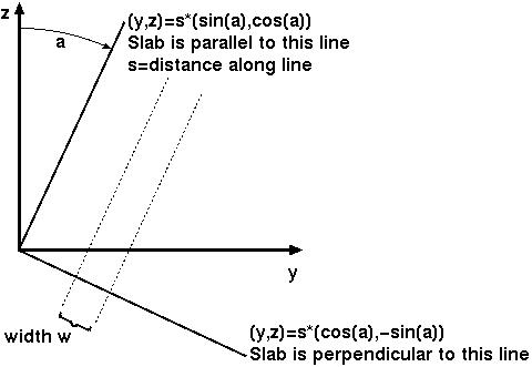
The set of points within the slab is described by the inequality
abs(y*cos(a)-z*sin(a)-s) < w/2
for angle="a", slab center offset="s", and slab width="w". To render a slanted coronal slab 30 mm thick, tilted posteriorly by 25 degrees, we could use this for the cutout expression:
abs(y*cosd(25)-z*sind(25)-20)-15
where the "sind()" and "cosd()" functions take arguments in degrees, and where I have chosen the offset to be 20 mm (you will have to alter this to get the exact position you want). Below, the renderer controls and resulting rendered image are shown.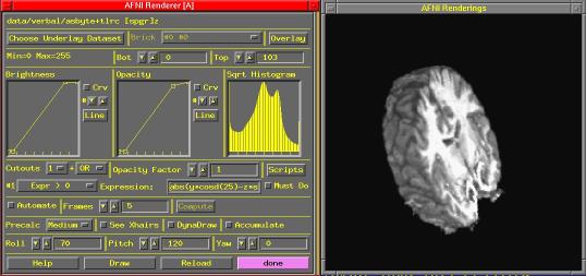
-
The above is for slanting in the yz-plane: for obliques that are between coronal and axial. If you want obliques that are between coronal and sagittal, then you are slanting in the xy-plane, and the roles of (y,z) in the above discussion are replaced by (x,y) respectively. Similarly, if you want obliques that are between axial and sagittal, then you are slanting in the xz-plane, and the roles of (y,z) in the above discussion should be replaced by (x,z) respectively.
-
If you want "double obliques", then you'll have to figure out the expression yourself. In such a case, I suggest studying up on 3D orthogonal matrices.

[Answer added 27 Aug 2001]
What is the format of the TTatlas+tlrc dataset?
Q80. What is the format of the TTatlas+tlrc dataset?
This dataset stores the Talairach Daemon database, as implemented into AFNI. A detailed description of its format is given here.
[Answer added 25 Oct 2001]
Can I send you some data?
Q81. Can I send you some data?
That can be arranged. I'll need some e-mail explaining why you want to send data. The full instructions can be found at the bottom of the AFNI Message Board.
[Answer added 03 Nov 2001]
What are your pet peeves about FMRI?
Q999. What are your pet peeves about FMRI?
- Abbreviating "Functional Magnetic Resonance Imaging" as "fMRI" rather than "FMRI".
- Referring to the analysis of functional image data as "functional analysis" (which is an entirely separate branch of mathematics over 80 years old).
- People who don't ever read the manuals, README.* files, or use the "BHelp" feature in AFNI, but instead bug me with questions like, "What does this button here do?" (that is to say, virtually everyone).
- The sentence, "I have a quick question" (particularly when uttered by anyone whose initials are PAB).
Ciao - Bob Cox
[last update to this file: 29 Apr 2002]


